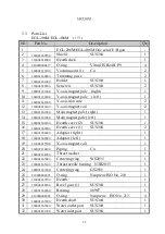
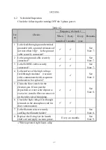

SECTION 4
23
(6)
When the abnormal discharge has stopped, increase the emission current
slowly.
The filament will light. Set the emission current to 50 mA. The beam spot
will be seen in the hearth. Position the beam spot in the center of the
crucible. Here, bluish white light might be seen around the crucible. This
is attributed to light emission caused by a small amount of scattered electrons
and secondary electrons hitting the contaminants or oxide film on the crucible
surface.
(7)
With the positioning of the beam spot being completed, increase the
emission current until evaporant is red heated.
Sometimes, abnormal discharge occurs due to the gas emitted from the
evaporant. In that event, do not try to apply power quickly, but take time.
Generally, degassing can be done more quickly by scanning with electron
beam.
(8)
Start deposition.
Increase the emission current up to a level at which evaporation is effected
and open the shutter when abnormal discharge has almost ceased and the
emission has become stable.
NOTE
For stable deposition, deposition rate control by deposition control equipment
is recommended.
(9)
When the coating of a desired thickness is obtained, close the shutter,
decrease the emission current, and switch off the high voltage.
It takes 15 to 20 minutes before the evaporant and filament holder cool down.
When the vacuum chamber is vented to atmospheric pressure, introducing
inert gas is recommended.
CAUTION
After operation of an EB GUN, EB GUN, especially an emitter assembly
periphery, evaporation material, filament cables and high voltage
feed-through terminals become high temperature. Take care not to burn
yourself.
Summary of Contents for EGL-206M
Page 2: ...EB0007 03e...
Page 3: ...EB0007 03e...
Page 10: ......
Page 13: ...SECTION 1 3 Fig 1 1 Dimensional Drawing for EGL 206M EGL 406M...
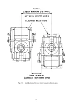
Page 24: ...SECTION 3 14 Fig 3 1 Installation of two or more electron beam guns...
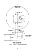
Page 26: ...SECTION 3 16 Fig 3 3 Typical water cooling piping arrangement...
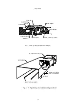
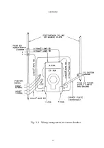
Page 27: ...SECTION 3 17 Fig 3 4 Wiring arrangement in vacuum chamber...
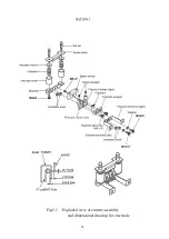
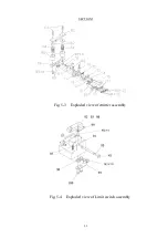
Page 38: ...SECTION 5 28 Fig 5 1 Exploded view of emitter assembly and dimensional drawing for electrode...
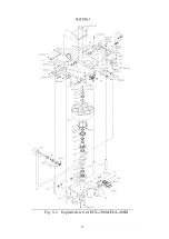
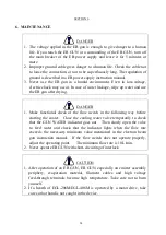
Page 42: ...SECTION 5 32 Fig 5 2 Exploded view of EGL 206M EGL 406M...


