background image


SECTION 5 

29 


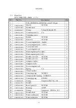
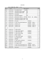
  5.3  Parts List 
 

EGL-206M/EGL-406M    ( 1/3 ) 

No. 

Part No. 

Description 

Q

ty 

  EGL-206M/EGL-406M One set of E/B gun 

200001660700 

  Shield   

SUS304 

210004014000 

  Hearth deck 

C10000000417 

  O-ring 

Viton JIS B2401 P9 

200001615100 

  Vacuum joint (1) 

Cu 

200001660900 

  Trimming piece 

200001661000 

  Holder 

SUS304 

210004030200 

  Setscrew 

SUS304 

200001661200 

  Y-axis magnet pole    (right) 

10 

200001661400 

Y-axis magnet pole    ( left ) 

11 

200001661600 

  Y-axis iron core 

12 

210004016100 

  Y-axis magnet coil 

13 

200001661800 

  Main magnet pole ( right ) 

14 

200001662000 

  Main magnet pole ( left ) 

15 

200001662100 

  Hearth cover (2) 

SUS304 

16 

200001662200 

  Hearth cover (1) 

SUS304 

17 

200001662400 

  Adaptor ( right ) 

18 

200001662600 

  Adaptor ( left ) 

19 

210004015500 

  X-axis magnet coil 

20 

200007218400 

  Piping 

Cu 

21 

200001662900 

  Thrust washer 

22 

200001663000 

  Centering ring          WS2035 

23 

200001663100 

  Thrust needle bearing    NTB2035 

24 

200001663200 

  Centering ring   

GS2035 

25 

C10000000001 

  O-ring 

Neoprene ISO No. 210 

26 

210004039700 

  Hearth 

27 

210004030300 

  Bevel gear (1) 

SUS304 

28 

200001663400 

  Bearing 

#6907 

29 

C10000000002 

  O-ring 

Neoprene    ISO No. 213 

30 

200001663500 

  Hearth shaft       

SUS304 

31 

200001663600 

  Water outlet port       SUS304 

32 

200001663700 

  Water inlet port 

SUS304 

Summary of Contents for EGL-206M

Page 1: ...INSTRUCTION MANUAL MULTI HEARTH ELECTRON BEAM SOURCS model EGL 206M EGL 406M 4nd edition 2023 08 01 ULVAC Inc Read this manual before operation this product Keep this manual at your hand for immediate...

Page 2: ...EB0007 03e...

Page 3: ...EB0007 03e...

Page 4: ...beam source before you fully understand them Carefully read and fully understand Safety Cautions and Safety Read this manual until you fully understand it and can operate the power supply correctly K...

Page 5: ...tenance or inspection Never try to operate an electron beam source before you read sections on operation inspection and maintenance and fully understand them 3 Safety denotations are used throughout t...

Page 6: ...damage to the equipment NOTICE Failure to comply with this involves the possibility of damage to or short life of the equipment It is hardly possible to predict all potential dangers in operation ins...

Page 7: ...e majeure are not covered by this warranty Consumable parts which are not covered by the warranty 1 Filament 210004027700 2 Insulator 210004028100 3 Insulation bush 210004028200 4 Fixed insulator 2100...

Page 8: ...for units older than five years may not be readily available because their production may have been discontinued In that event repair will take longer FOR DISPOSAL Please comply with the state regulat...

Page 9: ...MOUNTING THE ELECTRON BEAM GUN 6 3 1 Necessary Equipment 6 3 2 Installation of Electron Beam Gun 8 3 3 Safeguards against X Rays See Fig 3 5 13 4 OPERATION 19 4 1 Check before Operation 19 4 2 Operat...

Page 10: ......

Page 11: ...obtained A normal heat resistance evaporation source needs frequent replacement of the filament the boat etc depending on the evaporation material whereas an electron beam evaporation source is essen...

Page 12: ...e 1 6 m min or more Ribbon beam Al 8 kW 250H directly above hearth Crucible of 40cc Amount of cooling water 10L min or more 0 7MPa max Water temperature 15 C 25 C Hearth position detecting mechanism N...

Page 13: ...SECTION 1 3 Fig 1 1 Dimensional Drawing for EGL 206M EGL 406M...

Page 14: ...g After the electron beam gun and all standard accessories have been taken out from the case check the following If the electron beam gun is already mounted in the coater open the chamber so that the...

Page 15: ...210004027700 2 Insulator D 12 mm L 22 mm 210004028100 4 Insulation bushing OD 8 mm ID 4 mm L 3 5mm 210004028200 2 Fixed insulator OD 5 ID 4 mm L 6 5mm 210004028300 2 Filament setscrew M4 6 2100040240...

Page 16: ...mber wall and connect it to the gun by means of a copper strip Outside the chamber the bolt is connected to the earth cable and ground cable of the E B power supply ULVAC recommends the use of ERZ 003...

Page 17: ...er pressure requirement is 3 to 3 5 kg cm2 or more which slightly varies with piping arrangement and length If water flow rate is not enough pressurization by installing a pressor pump near the deposi...

Page 18: ...arth rotation mechanism The hearth drive shaft can be installed in one of three directions Since it is installed in the rear as standard it will be necessary to disassemble and reinstall it if install...

Page 19: ...filament is mounted in the same direction Even if these actions are taken the beam spot may be deformed slightly or the beam may not be deflected over the entire surface of the crucible 4 High voltage...

Page 20: ...3 2 Cover the filament cables with a SUS304 stainless steel cover 0 4 to 1 0 mm Since the filament cables are energized with a high voltage of 10 kVDC in maximum keep a spacing of 15 mm or more betwe...

Page 21: ...uses a magnetic float which may be deposited with iron powder Periodically disassemble and clean it 2 The pressure switch has been so set that it is turned ON at 3 kg cm2 and OFF at 2 5 kg cm2 by ini...

Page 22: ...uch that the heat source is not activated unless cooling water is fed to the hearth and coil 10 Grounding Class A grounding ground resistance of 10 or less is recommended See the electron beam gun pow...

Page 23: ...e of X rays may leak defending on the thickness of the gasket X rays can be harmful to the human body if exposed for a long time For safety ULVAC recommends the following methods View port glass Use P...

Page 24: ...SECTION 3 14 Fig 3 1 Installation of two or more electron beam guns...

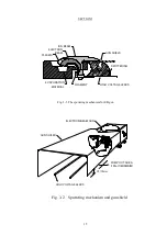
Page 25: ...MATERIAL FILAMENT HIGH VOLTAGE LEADS SPUTTERING GUN SHIELD ELECTRON BEAM Fig 3 3 The sputtering mechanism for EB gun H 15mm PUMP OUT AREA 100 MINIMUM HIGH VOLTAGE LEADS GUN SHILED ELECTRON BEAM GUN Fi...

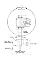
Page 26: ...SECTION 3 16 Fig 3 3 Typical water cooling piping arrangement...

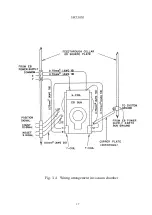
Page 27: ...SECTION 3 17 Fig 3 4 Wiring arrangement in vacuum chamber...

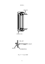
Page 28: ...SECTION 3 18 VIEW PORT LEADEN GLASS X RAY SUS304 SHIELD GASKET BELLJAR TARGET Fig 3 5 X ray shield...

Page 29: ...he filament cables If the distance between these wires is not more than 20 mm arc discharge of the high voltage will take place and the power supply may fail 2 Never wire the deflection coils in the w...

Page 30: ...rotate smoothly 7 Is the height of the shutter appropriate CAUTION The shutter must be located at least 70 mm above the top of the crucible 8 Is the crucible visible through the view port 9 Are the t...

Page 31: ...g the beam spot to the center of the crucible and charge the crucible with evaporatnt more than 3 4 of its capacity For evaporant with high heat conductance bring the beam spot to the center of the cr...

Page 32: ...power supply is so designed that it automatically lowers the high voltage if an overcurrent is produced due to discharge and the high voltage is restored after the discharge has ceased If the dischar...

Page 33: ...ickly but take time Generally degassing can be done more quickly by scanning with electron beam 8 Start deposition Increase the emission current up to a level at which evaporation is effected and open...

Page 34: ...ament cables and high voltage feed through terminals become high temperature Take care not to burn yourself 2 Removing the filament The filament can be removed by loosening the filament setscrews alte...

Page 35: ...ve oxide film 2 Dust remaining in the filament or in the component parts of the emitter assembly causes short circuiting of the filament Clean them carefully 3 Replace the emitter assembly periodicall...

Page 36: ...utious in the work 2 There is a clearance of 1 mm between the hearth deck and hearth Powder or fragments of evaporant may fall in between them In that event disassemble the electron beam gun and remov...

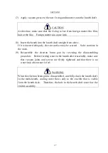
Page 37: ...y be scarred So be cautious in the work 9 Reassemble the electron beam gun by reversing the disassembling procedure Before feeding water to the hearth after reassembly make sure that vacuum joints and...

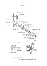
Page 38: ...SECTION 5 28 Fig 5 1 Exploded view of emitter assembly and dimensional drawing for electrode...

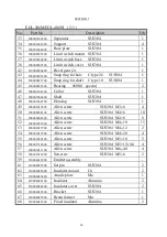
Page 39: ...net pole right 1 14 200001662000 Main magnet pole left 1 15 200001662100 Hearth cover 2 SUS304 1 16 200001662200 Hearth cover 1 SUS304 2 17 200001662400 Adaptor right 1 18 200001662600 Adaptor left 1...

Page 40: ...ng SUS304 1 49 200003019800 Allen screw SUS304 M3 6 4 50 200000604100 Allen screw SUS304 M4 6 10 51 200000604200 Allen screw SUS304 M4 8 8 52 200003029600 Allen screw SUS304 M4 10 15 53 200003029700 A...

Page 41: ...00000604200 Allen screw SUS304 M4 8 2 80 200003029600 Allen screw SUS304 M4 10 2 81 200003029700 Allen screw SUS304 M4 12 2 90 20008868700 Limit switch 1 91 20008868800 Limit switch mount SUS304 1 92...

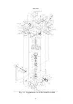
Page 42: ...SECTION 5 32 Fig 5 2 Exploded view of EGL 206M EGL 406M...

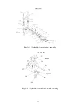
Page 43: ...SECTION 5 33 Fig 5 3 Exploded view of emitter assembly Fig 5 4 Exploded view of Limit switch assembly...

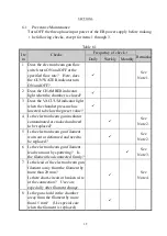
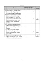
Page 44: ...heck of the flow switch in the following way before starting the coater Close the cooling water valve temporarily to check that the GUN WATER indicator goes out Then slowly open the valve to feed wate...

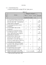
Page 45: ...he chamber pressure has lowered to below the preset value 4 Is the electron beam gun insulator contaminated or cracked and need to be replaced See Note 2 5 Is the electron beam gun filament worn out o...

Page 46: ...if screws are oxidized with heat and insulation covering on the cable side is melted in a dangerous condition See Note 5 11 Are all parts energized with high voltage covered and protected to prevent a...

Page 47: ...See Note 7 4 Is the surface of the high voltage feed through insulator vacuum side contaminated with evaporant and needs to be replaced See Note 2 5 Clean the flow switch for the electron gun If iron...

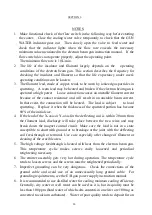
Page 48: ...e it when the thickness of the sputtered portion has become 80 of the initial size 4 If the lead of the X axis or Y axis for the deflecting coil is within 20 mm from the filament lead discharge will t...

Page 49: ...he multi hearth type electron beam gun uses an O ring for the shaft seal to seal water and vacuum To the O ring is applied vacuum grease as lubricant but there can be a leak due to shortage of grease...

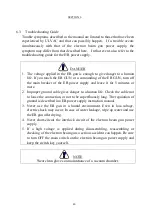
Page 50: ...it for 5 minutes or more 2 Improper ground cable gives danger to a human life Check the cable not to loose the connection or not to be superfluously long The regulation of ground is described in a EB...

Page 51: ...rt circuit of filament and beam former b Check if metal particles are caught in the filament holder c Check the filament lead for short circuit d Check if the specified filament setscrews are used Too...

Page 52: ...t sometimes moves A Unstable focus current of EB power supply a Check the deflection coil lead for contact and insulation b Failure of E B power supply See its instruction manual 5 The beam spot moves...

Page 53: ...he hearth is perforated a Replace the hearth 11 Frequent abnormal discharge Frequency of abnormal discharge increases when power is applied above a certain level A The gun shield is not provided a Pro...

Page 54: ...orant B Increased ripple in the high voltage 5 p p or more a Check if oscillation occurs in the high voltage circuit of the power supply See its instruction manual b It is likely that radio frequency...

Page 55: ...e filament cable terminal is tight If loose retighten it d Check if the screw on the atm side of the high voltage feed through terminal is tight B Saturated emission current due to low setting of the...

Reviews: