Compressor Unit Instruction Manual
Appendix B
SCHEMATIC DIAGRAM
◆
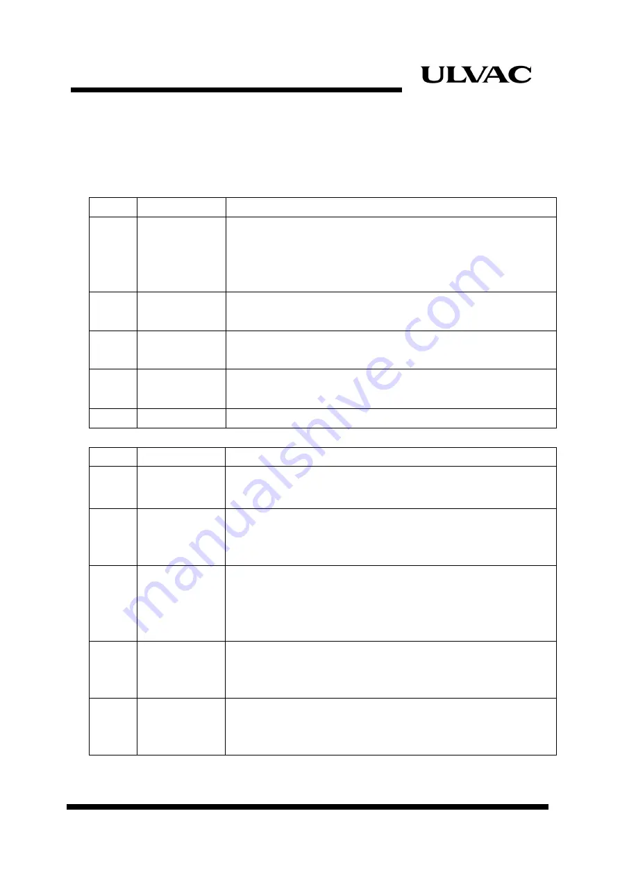
Safety Devices (in the control module)
Sign Item
Function
and
specification
MPB Over
current
protective switch
(AUTO RESET)
Automatically stops the compressor operation if a overcurrent
occurs due to overloading, or an abnormal rise of temperature inside
controller occurs. Both “TOP(PB1)” and “START(PB2) push-button
switch” light OFF.
CP1 Circuit
protector
(MANUAL RESET)
Shuts power off if a short circuit of compressor unit occurs.
Rated current: 15A
CP2 Circuit
protector
(MANUAL RESET)
Shuts power off if a short circuit of cold head occurs.
Rated current: 1A
PRR Reverse
phase
protective relay
Disables to start the unit when the power wires are connected in
reverse phase.
F Fuse
250V,
1A
◆
Safety Devices (others)
Sign Item
Function
and
specification
TS1
Thermal switch
Automatically stops the compressor operation if the oil flow rate is
insufficient. “STOP push-button switch (PB1) “lights ON.
TS2
Thermal switch
Stops the compressor operation if the cooling water flow rate is
significantly lowered, or there is no cooling water inside the
compressor unit.
“STOP push-button switch (PB1)” lights ON.
MPA Over
current
protective switch
Located on top of the compressor. Automatically stops the
compressor operation if a overcurrent occurs due to overloading, or
an abnormal rise of temperature inside compressor unit occurs.
“STOP push-button switch (PB1)” lights ON.
―
Pressure relief
valve
Located in the helium supply line. Operates automatically to discharge
the high over-pressure helium inside.
Set pressure: 2.41MPa(gage) (350psig)
―
Differential
pressure
regulating valve
Located in the line between the supply and return helium lines.
Regulates the maximum differential pressure during operation.
Set pressure: 1.34MPa(gage) (195psi)
ULVAC CRYOGENICS INCORPORATED
B-1
Summary of Contents for C10T
Page 2: ......
Page 8: ...F 6 ULVAC CRYOGENICS INCORPORATED This page intentionally left blank ...
Page 14: ...S 4 ULVAC CRYOGENICS INCORPORATED This page intentionally left blank ...
Page 16: ...IW 2 ULVAC CRYOGENICS INCORPORATED This page intentionally left blank ...
Page 32: ...Operation 4 2 ULVAC CRYOGENICS INCORPORATED This page intentionally left blank ...
Page 44: ...Troubleshooting A 4 ULVAC CRYOGENICS INCORPORATED This page intentionally left blank ...
Page 47: ...Compressor Unit Instruction Manual ULVAC CRYOGENICS INCORPORATED B 3 B 4 ...
Page 48: ...Compressor Unit Instruction Manual ULVAC CRYOGENICS INCORPORATED B 5 B 6 ...
Page 50: ...Flexible Hose C 2 ULVAC CRYOGENICS INCORPORATED This page intentionally left blank ...
Page 54: ...CS 2 ULVAC CRYOGENICS INCORPORATED This page intentionally left blank ...
Page 56: ...This page intentionally left blank R 2 ULVAC CRYOGENICS INCORPORATED ...


