VLS Service Manual - REV2015.04
Component Removal and Replacement
Page | 40
Component Removal and Replacement
Rulers
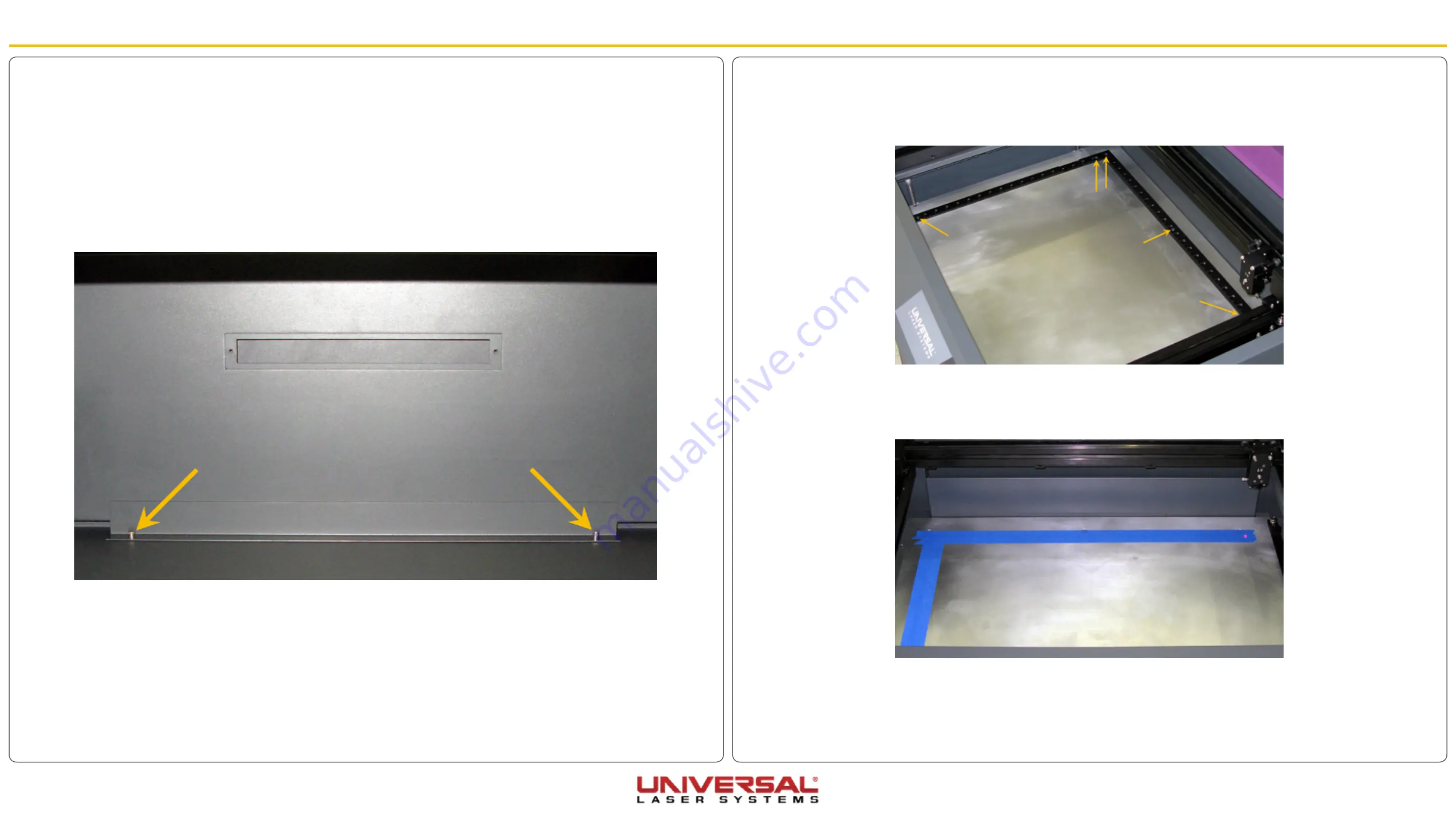
1. Remove all 5 screws securing the rulers to the engraving table and set them aside.
2. Use solvent cleaner to remove any debris left over from the removed rulers.
3. Place masking tape on the table over the approximate location of the ruler positions extending the full
length of the table on both axes.
4. Using your graphic software, create a red line box that outlines the page size perfectly.
5. Run that cut file (using paper settings) to determine the exact location for the edges of the rulers.
Exhaust Plenum
1. Power ON the laser system and the UCP.
2. Remove any material or accessories from the engraving table.
3. Using the Z-axis buttons on the keypad or UCP, raise the Z-axis table as high as possible.
4. Power OFF and unplug the system. Open the front door to its resting position.
5. Locate and remove the two (VLS3.60 and VLS4.60) or four (VLS6.60) socket head cap screws found
inside the laser system at the bottom back of the Frame.
6. Using both hands, reach in and grasp the exhaust plenum.
7. Lift the plenum clear of the two flat head screws on which they are resting. Tilt the bottom of the plenum
toward you and remove it from the system.
8. Installation is opposite of removal. Verify that the plenum is resting correctly on the two flat head screws.
Summary of Contents for VLS Series
Page 1: ...VLS Service Manual...


