
SARA-G450 - System integration manual
UBX-18046432 - R08
Design-in
Page 95 of 143
C1-Public
4
V_INT
TxD
Application Processor
(3.0V DTE)
RxD
RTS
CTS
DTR
DSR
RI
DCD
GND
SARA-G450
(1.8V DCE)
12
TXD
9
DTR
13
RXD
10
RTS
11
CTS
6
DSR
7
RI
8
DCD
GND
1V8
B1
A1
GND
U1
B3
A3
VCCB
VCCA
Unidirectional
voltage translator
C1
C2
3V0
DIR3
DIR2
OE
DIR1
VCC
B2
A2
B4
A4
DIR4
TP
0
Ω
TP
0
Ω
TP
0
Ω
TP
0
Ω
TP
21
VSEL
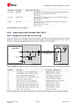
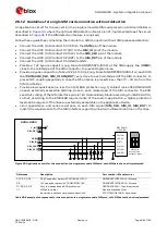
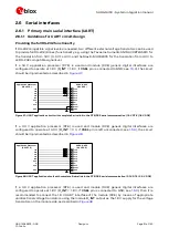
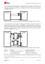
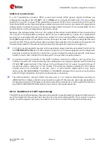
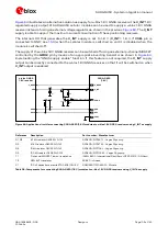
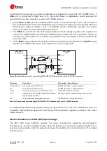
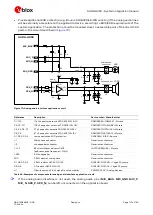
Figure 55: UART application circuit with partial V.24 link (5-wire) in the DTE/DCE serial interface (3.0 V DTE / 1.8 V DCE)
Reference
Description
Part number – Manufacturer
C1, C2
100 nF capacitor ceramic X7R 0402 10% 16 V
GRM155R61A104KA01 – Murata
U1
Unidirectional voltage translator
SN74AVC4T774
16
- Texas Instruments
Table 34: Parts for UART application circuit with partial V.24 link (5-wire) in DTE/DCE serial interface (3.0 V DTE / 1.8 V DCE)
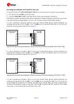
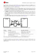
Providing the TXD and RXD lines only
If the functionality of the RTS, CTS, DTR, DSR, DCD and RI lines is not required in the application, or
the lines are not available:
Connect the module RTS input line to GND or to the CTS output line, since the module requires
RTS active (low electrical level) if HW flow control is enabled (AT&K3, which is the default setting).
The pin can be connected using a 0
Ω
series resistor to GND or to the active module CTS (low
electrical level) when the module is in active mode, the UART interface is enabled and the HW flow
control is enabled.
Connect the module DTR input line to GND.
Leave the DSR, DCD and RI output lines of the module unconnected and floating.
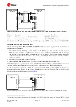
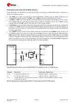
If RS-232 compatible signal levels are needed, the Maxim 13234E voltage level translator can be used.
This chip translates voltage levels from 1.8 V / 3.0 V (module side) to the RS-232 standard.
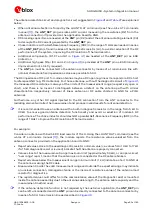
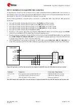
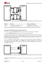
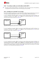
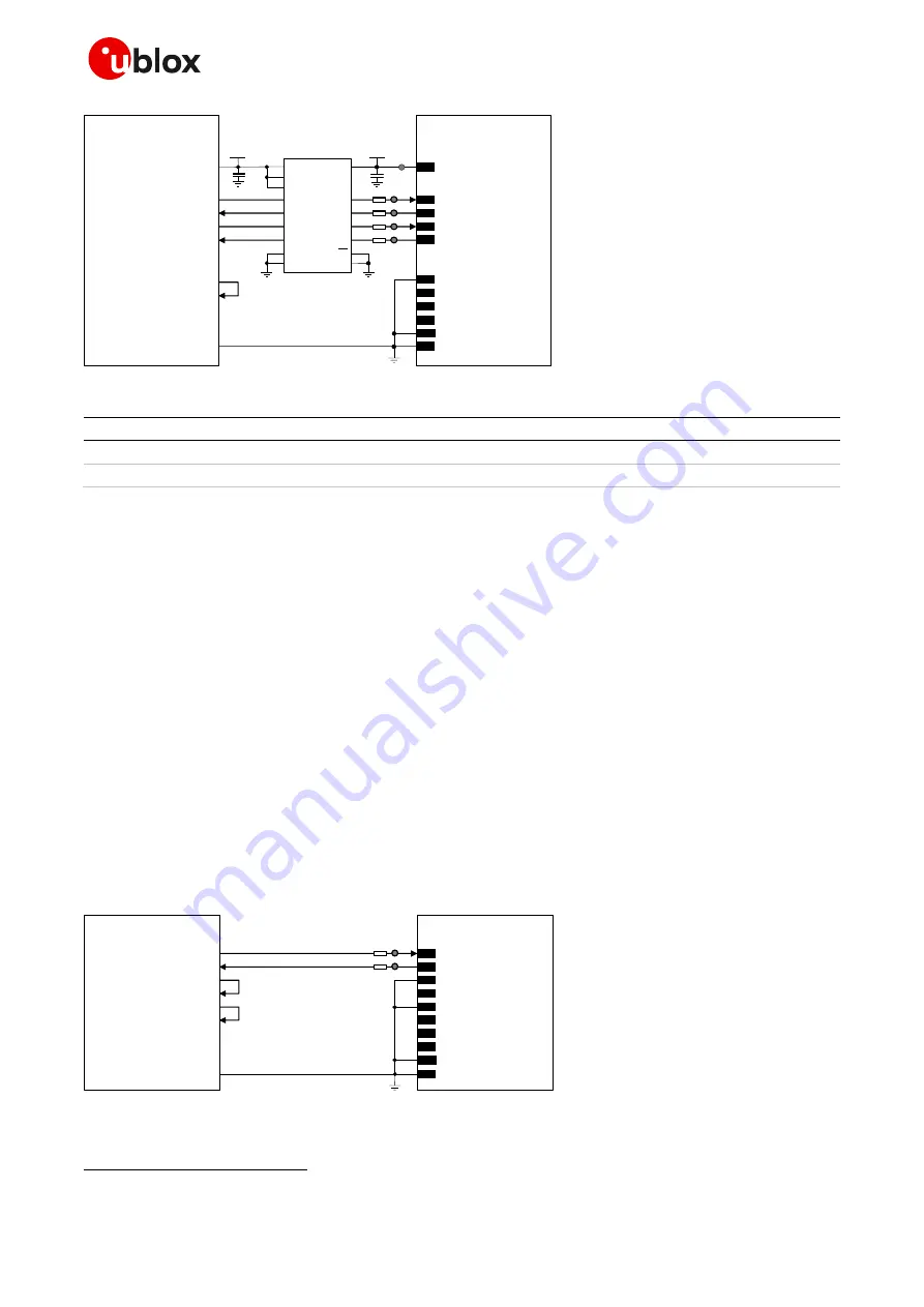
If a 1.8 V application processor (DTE) is used and module (DCE) generic digital interfaces are
configured to operate at 1.8 V (V_INT = 1.8 V, if VSEL pin is connected to GND; see
), the circuit
should be implemented as described in
TxD
Application Processor
(1.8V DTE)
RxD
RTS
CTS
DTR
DSR
RI
DCD
GND
SARA-G450
(1.8V DCE)
12
TXD
9
DTR
13
RXD
10
RTS
11
CTS
6
DSR
7
RI
8
DCD
GND
0
Ω
TP
0
Ω
TP
21
VSEL
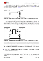
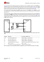
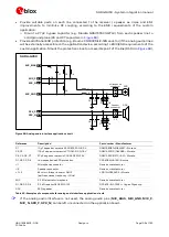
Figure 56: UART application circuit with partial V.24 link (3-wire) in the DTE/DCE serial interface (1.8 V DTE / 1.8 V DCE)
16
Voltage translator providing partial power-down feature so that DTE 3.0 V supply can be ramped up before V_INT 1.8 V supply


