


SARA-G450 - System integration manual
UBX-18046432 - R08
Design-in
Page 106 of 143
C1-Public
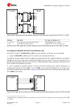
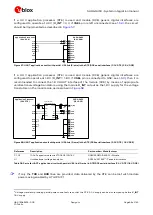
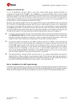
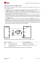
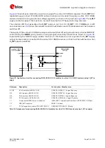
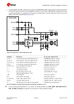
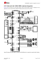
If SARA-G450 module’s generic digital interfaces are configured to operate at 1.8 V (V_INT = 1.8 V, if
VSEL pin is connected to GND; see
shows an application circuit example for
connecting the cellular module to a u-blox 3.0 V GNSS receiver:
As the SDA and SCL pins of the SARA-G450 module are not tolerant up to 3.0 V, the connection
to the related I2C pins of the u-blox GNSS receiver must be provided using an appropriate I2C-bus
bidirectional voltage translator (e.g. TI TCA9406, which additionally provides the partial
power-down feature), with suitable pull-up resistors.
The GPIO2 is connected to the active-high enable pin of the voltage regulator that supplies the
u-blox 3.0 V GNSS receiver providing the “GNSS supply enable” function. A pull-down resistor is
provided to avoid a switch-on of the positioning receiver when the cellular module is switched off
or in reset state.
The V_BCKP supply output of the cellular module can be directly connected to the V_BCKP supply
input pin of the GNSS receiver as in the application circuit of
u-blox GNSS
3.0 V receiver
R1
IN
OUT
GNSS LDO
regulator
SHDN
R2
VMAIN
3V0
U1
23
GPIO2
26
SDA
27
SCL
R4 R5
1V8
SDA_A
SDA_B
GND
U2
SCL_A
SCL_B
VCCA
VCCB
I2C-bus bidirectional
voltage translator
4
V_INT
C1
C2
C3
R3
SDA2
SCL2
VCC
2
V_BCKP
V_BCKP
OE
GNSS supply enable
GND
SARA-G450
(1.8 V)
21
VSEL
Figure 68: Application circuit for connecting SARA-G450 (1.8 V) modules to u-blox 3.0 V GNSS receivers
Reference
Description
Part number - Manufacturer
R1, R2, R4, R5
4.7 k
Ω
resistor 0402 5% 0.1 W
RC0402JR-074K7L - Yageo Phycomp
R3
47 k
Ω
resistor 0402 5% 0.1 W
RC0402JR-0747KL - Yageo Phycomp
C2, C3
100 nF capacitor ceramic X5R 0402 10% 10V
GRM155R71C104KA01 - Murata
U1, C1
Voltage regulator for GNSS receiver and related
output bypass capacitor
See GNSS receiver hardware integration manual
U2
I2C-bus bidirectional voltage translator
TCA9406DCUR - Texas Instruments
Table 42: Components for connecting SARA-G450 (1.8 V) modules to u-blox 3.0 V GNSS receivers
For additional guidelines regarding the design of applications with u-blox 3.0 V GNSS receivers, see
the GNSS implementation application note
and the hardware integration manual of the u-blox
GNSS receivers.
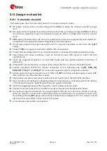
2.6.4.2
Guidelines for DDC (I2C) layout design
The DDC (I2C) serial interface requires the same consideration regarding electromagnetic
interference as any other digital interface. Keep the traces short and avoid coupling with RF line or
sensitive analog inputs, since the signals can cause the radiation of some harmonics of the digital
data frequency.


