


SARA-G450 - System integration manual
UBX-18046432 - R08
System description
Page 17 of 143
C1-Public
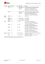
1.5.1.2
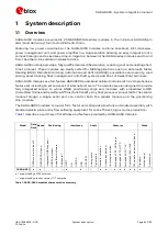
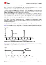
VCC current consumption in 2G connected mode
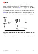
When a GSM transmission is established, the VCC consumption is determined by the current
consumption profile typical of the GSM transmitting and receiving bursts.
The current consumption peak during a transmission slot is strictly dependent on the transmitted
power, which is regulated by the network. The transmitted power in the transmit slot is also the more
relevant factor for determining the average current consumption.
If the module is transmitting in 2G single-slot mode (as in GSM talk mode) in the 850 or 900 MHz
bands, at the maximum RF power control level (approximately 2 W or 33 dBm in the Tx slot/burst), the
current consumption can reach a high peak / pulse (see the SARA-G450 data sheet
) for 576.9
µ
s
(width of the transmit slot/burst) with a periodicity of 4.615 ms (width of 1 frame = 8 slots/burst), so
with a 1/8 duty cycle according to GSM TDMA (Time Division Multiple Access).
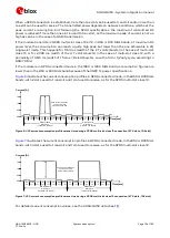
If the module is transmitting in 2G single-slot mode in the 1800 or 1900 MHz bands, the current
consumption figures are quite less high than the one in the low bands, due to the 3GPP transmitter
output power specifications.
During a GSM transmission, current consumption is not so significantly high in receiving or in monitor
bursts and it is low in the bursts unused to transmit / receive.
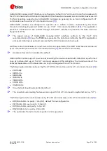
shows an example of the module current consumption profile versus time in GSM talk mode.
Time [ms]
RX
slot
unused
slot
unused
slot
TX
slot
unused
slot
unused
slot
MON
slot
unused
slot
RX
slot
unused
slot
unused
slot
TX
slot
unused
slot
unused
slot
MON
slot
unused
slot
GSM frame
4.615 ms
(1 frame = 8 slots)
Current [A]
200 mA
60-120 mA
1900 mA
Peak current depends
on TX power and
actual antenna load
GSM frame
4.615 ms
(1 frame = 8 slots)
1.5
1.0
0.5
0.0
2.0
60-120 mA
10-40 mA
Figure 4: VCC current consumption profile versus time during a GSM transmission (1 TX slot, 1 RX slot)
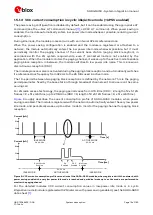
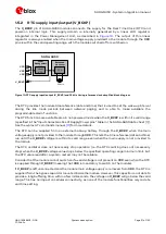
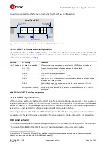
illustrates the VCC voltage profile versus time during a GSM transmission, according to the
related VCC current consumption profile described in
Time
undershoot
overshoot
ripple
drop
Voltage
3.8 V
(typ)
RX
slot
unused
slot
unused
slot
TX
slot
unused
slot
unused
slot
MON
slot
unused
slot
RX
slot
unused
slot
unused
slot
TX
slot
unused
slot
unused
slot
MON
slot
unused
slot
GSM frame
4.615 ms
(1 frame = 8 slots)
GSM frame
4.615 ms
(1 frame = 8 slots)
Figure 5: Description of the VCC voltage profile versus time during a GSM transmission (1 TX slot, 1 RX slot)


