background image

PAGE 17 OF 33 

1219 IH-8105

APPLICATIONS CONTINUED

The Check Configurations are defined below.

NOTE: Default settings are in bold.

CONFIGURE ITEM

OPTION

DESCRIPTION

Check Mode

Check Weighing

/Check 

Counting

Check weighing mode


Check counting mode

Auto Tare

Off

/On/Accept

Off:

 Auto tare is turned off. 

On: The first stable weight (>=5d) will be tared as a container automatically. 

Accept: If object weight is in the range of the Over and Under Limit you set, auto tare will 

be performed.

Accumulate

Off/

Manual/Automatic

Off:

 The icon "

Σ

" does not display. 

Manual: The softkey "

Σ

" displays. User can press the key to accumulate the stable weight. 

Automatic: The icon "

Σ

" displays. The weight will be accumulated automatically.

NOTE: The load to be accumulated has to be >= 10d. The next 
accumulation can only start once the pan is cleared.

When LFT is ON (no such limit when LFT is OFF or the approve mod is OIML), 

a. Gross weight and net weight cannot be accumulated; 

b. Gross 0 has to be reached before a new sample accumulation.

When LFT is OFF, 

a. Gross weight and net weight can be accumulated; 

b. A new sample can be accumulated after reaching gross 0 or net 0.

Audible Signal

Off/

Under and  

Over/Accept/Under/Over

Off:

 No beep. 

Under and Over/Accept/Under/Over: Beep when reaching the selected check point.

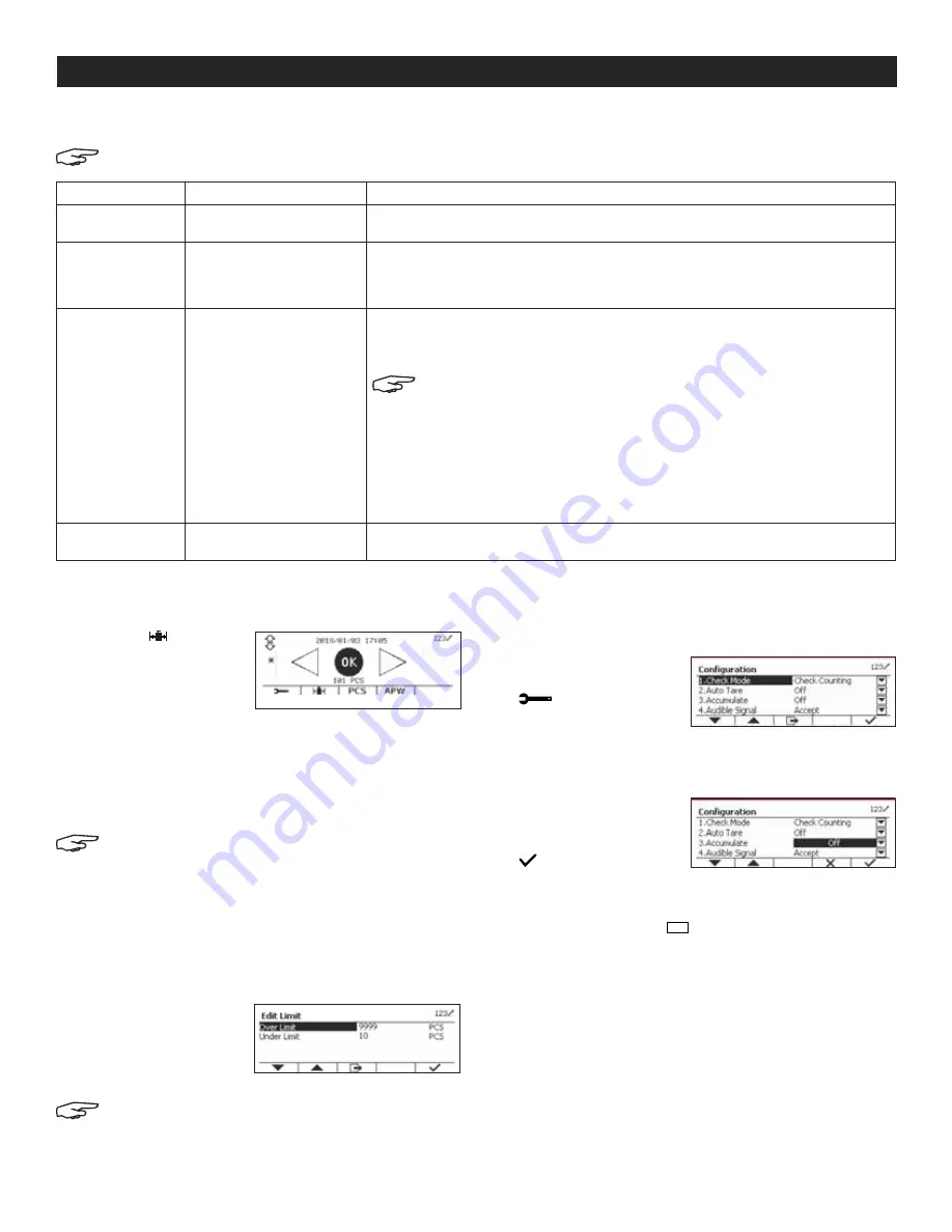
CHECK COUNTING

1.  Press the   button  

and select Check 

Mode to Check 

Counting.  

(See Figure 57)

2.  Place objects on pan. The Under/Accept/Over status 

is shown in the progress bar area, while the actual 

number of pieces is shown on the main display line. 

Set the Average Piece Weight (APW)

NOTE: It is recommended that the APW is larger 
than 1d. If APW is between 0.05d and 1d, a 
warning message will be displayed and the 
information line will show "APW is low!". If APW is 
less than 0.05d, an error message will appear 
and the APW value cannot be stored.

There are three methods to set the APW. See Application 

Setup at right.

Defining Over/Under Limits

Press the Edit Limit button  

to define counting limit. 

(See Figure 58)

wNOTE: See Check Weighing on page 17 for 
information on how to set the Over/Under limits.

APPLICATION SETUP

The application can be customized for user preferences

1.  Press the softkey 

corresponding to the 

 icon to enter the 

Configuration Setup. 

Configuration menu is 

now displayed.  

(See Figure 59)

2.  Select the list item 

and press the softkey 

corresponding to the 


icon, to change 

setting. (See Figure 60)

3.  To return to Application home screen, press the button 

corresponding to the 

Menu

User

 icon.

Figure 57

Figure 59

Figure 58

Figure 60

Summary of Contents for OHAUS DEFENDER 5000

Page 1: ...its Print Short press Send the current display value to the RS 232 port or option when properly enabled Long Press Change the current weighing unit Press and hold the key to scroll through the list of...

Page 2: ...1 a Switch between three input modes numeric lowercase and uppercase input OVERVIEW OF CONTROLS SETUP 1 Remove shipping spacers and place the weighing pan securely over the rubber load pads on the top...

Page 3: ...ate Edit Template Edit String Reset WiFi Bluetooth WiFi MAC Address Network Port DHCP IP Address Gateway DNS Subnet Mask Alternate Command Reset Bluetooth Device Name Print Setup Assignment Print Opti...

Page 4: ...FT set to ON 4 Allow the scale to warm up for approximately five minutes after stabilizing to room temperature 5 To abort calibration press the softkey corresponding to the X icon anytime during the c...

Page 5: ...to enter the Calibration submenu Scroll to Linearity Calibration using the softkey corresponding to the icon See Figure 14 3 Press the softkey corresponding to the icon to initiate Linearity Calibrati...

Page 6: ...10 19 02 7 7 6 6 5 5 4 4 3 3 2 19 02 20 45 8 7 7 6 6 5 5 4 4 3 3 20 45 22 22 8 8 7 7 6 6 5 5 4 4 3 22 22 23 54 9 8 8 7 7 6 6 5 5 4 4 23 54 25 21 9 9 8 8 7 7 6 6 5 5 4 25 21 26 45 10 9 9 8 8 7 7 6 6 5...

Page 7: ...6 26 25 85 45 90 00 31 30 30 29 29 28 28 27 27 26 26 OPERATION CONTINUED TABLE OF GEO VALUES CONTINUED SETUP MENU When the Indicator connects to a scale base for the first time enter this menu to set...

Page 8: ...tion for the second weighing range of the scale If Single interval is enabled this parameter will not be shown NOTE Graduation settings are limited to values from Capacity divided by 600 to Capacity d...

Page 9: ...intain zero until a change of one division per second is exceeded 3d Display will maintain zero until a change of three divisions per second is exceeded AUTO DIM Set the display backlight functionalit...

Page 10: ...late Discrete Output 1 Off Overload Underload Zero Discrete Output 2 Off Overload Underload Zero Discrete Output 3 Off Overload Underload Zero Discrete Output 4 Off Overload Underload Zero Counting En...

Page 11: ...actor multiplier 3 divide the Factor by 1 000 1x10 3 2 divide the Factor by 100 1x10 2 1 divide the Factor by 10 1x10 1 0 multiply the Factor by 1 1x100 1 multiply the Factor by 10 1x101 2 multiply th...

Page 12: ...ss the button Mode to select an activated application The current application will be shown in the upper left corner of the home screen The Indicator incorporates the following applications WEIGHING U...

Page 13: ...esults 1 To view accumulation results press the softkey corresponding to the icon The Accumulate Result screen is displayed See Figure 31 2 To clear accumulation results press the Off On CLR button Se...

Page 14: ...umber of pieces SET THE AVERAGE PIECE WEIGHT APW NOTE It is recommended that the APW is larger than 1d If APW is between 0 05d and 1d a warning message will be displayed and the information line will...

Page 15: ...late Off Automatic Manual Off The icon does not display Manual The softkey displays User can press the key to accumulate the stable weight Automatic The icon displays The weight will be accumulated au...

Page 16: ...Figure 54 CHECK Check is used to compare the weight or pieces of a sample against target limits Press the Mode Library button until the icon corresponding to Check is displayed on the screen Two diffe...

Page 17: ...and Over Accept Under Over Off No beep Under and Over Accept Under Over Beep when reaching the selected check point CHECK COUNTING 1 Press the button and select Check Mode to Check Counting See Figure...

Page 18: ...e stable weight Automatic The icon displays The weight will be accumulated automatically NOTE The load to be accumulated has to be 10d The next accumulation can only start once the pan is cleared When...

Page 19: ...e Figure 65 2 Press the softkey corresponding to the icon for confirmation See Figure 66 Method 2 1 Press the softkey corresponding to the icon to enter the submenu for setting reference weight See Fi...

Page 20: ...list and highlight Application Mode See Figure 72 2 Enter this submenu by pressing the button corresponding to the icon See Figure 72 3 In the Application Mode menu enter the Percent submenu See Figu...

Page 21: ...e placed on the pan first After the terminal has done taring automatically place load on the pan to start dynamic weighing Start Weight 3 000 with current unit If the operation type is Semi Automatic...

Page 22: ...s setup will only work when the I O Option board has been installed The option I O board provides two isolated inputs and four dry contact normally open relay outputs which can be used for simple pro...

Page 23: ...table Only Off On LFT Force On Auto On Stable Mode Load Load and Zero Auto On Accept Interval Time 1 50 000 MT Continuous OH Continuous SICS Reference Balance Select Template Simple Custom 1 Custom 2...

Page 24: ...lected and weighing mode is Check values will be printed when weight is accepted ACCEPT Printing occurs each time the display is within the Checkweigh accept range and stability criteria are met INTER...

Page 25: ...minate a template an End of Template field must be included All fields after the End of Template field will be ignored Figure 87 Figure 88 ITEM LENGTH ITEM LENGTH 3 spaces 3 String 1 Not fixed up to 4...

Page 26: ...structure 3 Displayed weight Either gross or net weight Six digits no decimal point or sign Insignificant leading zeroes are replaced with spaces 4 Tare weight Six digits of tare weight data No decim...

Page 27: ...re xxx is the value under current unit CO xxx Set Over Limit only in Check mode where xxx is the value under current unit x Set Counting APW x in grams only in Counting or Check Counting mode must hav...

Page 28: ...nt weight value immediately SIRU Send weight value in the current unit immediately and repeat SIU Send weight value in the current unit immediately SNR Send stable weight value and repeat after every...

Page 29: ...ify communication by pressing the print button NOTE If HyperTerminal is set up properly the value on the display will be shown in the window CONNECTING TO A SERIAL PRINTER Connect the cable supplied w...

Page 30: ...used to separate the other fields The Weight1 field is four right justified characters If the value is negative the character is located at the immediate left of the most significant digit The Unit1...

Page 31: ...k on the terminal BATTERY OPERATION During operation battery icon indicates charge level remaining The battery icon is located above weighing unit on indicator display See Figure 94 NOTE When battery...

Page 32: ...verification procedure SEALING The local weights and measures official or authorized service agent must apply a security seal to prevent tampering with the settings Refer to the illustrations below fo...

Page 33: ...ected menu to off in the Lock menu Lockout Switch on the circuit board may need to be set to the off position Error 8 1 Weight reading exceeds Power On Zero limit Remove load from scale Recalibrate sc...

Reviews: