


SARA-G3 series - System Integration Manual
UBX-13000995 - R06
Objective Specification
Design-in
Page 134 of 218
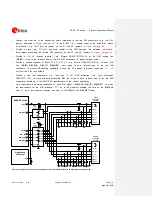
the module. If the external signals connected to the wireless module cannot be tri-stated or set
low, insert a multi channel digital switch (e.g. Texas Instruments SN74CB3Q16244, TS5A3159, or
TS5A63157) between the two-circuit connections and set to high impedance during module power
down mode and during the module power-on sequence.
ESD sensitivity rating of UART interface pins is 1 kV (Human Body Model according to JESD22-
A114). Higher protection level could be required if the lines are externally accessible on the
application board. Higher protection level can be achieved by mounting an ESD protection (e.g.
EPCOS CA05P4S14THSG varistor array) close to accessible points.
2.5.1.2
Guidelines for UART layout design
The UART
serial interface requires the same consideration regarding electro-magnetic interference as any
other digital interface. Keep the traces short and avoid coupling with RF line or sensitive analog inputs,
since the signals can cause the radiation of some harmonics of the digital data frequency.
2.5.2
Auxiliary asynchronous serial interface (UART AUX)
2.5.2.1
Guidelines for UART AUX circuit design
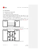
The auxiliary UART interface can be connected to an application processor if it can be set in pass-
through mode so that the auxiliary UART interface can be accessed for SARA-G3 modules’ firmware
upgrade by means of the u-blox EasyFlash tool and for Trace log capture (debug purpose).
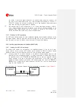
To directly enable PC (or similar) connection to the module for firmware upgrade using the u-blox
EasyFlash tool and for debugging purposes, it is highly recommended to provide direct access on
the application board to the
TXD_AUX
and
RXD_AUX
pins, by means of accessible testpoints
directly connected to the pins of the module. Also provide access to the
V_INT
pin to make
possible the voltage translation to the auxiliary UART interface voltage level, and to the
PWR_ON
or
RESET_N
pins, or enable the DC supply connected to the
VCC
pin to start the firmware upgrade
using the u-blox EasyFlash tool.
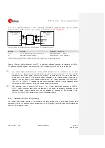
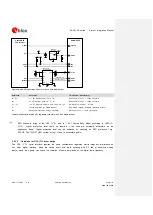
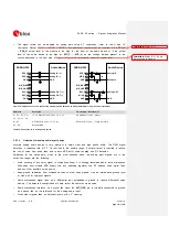
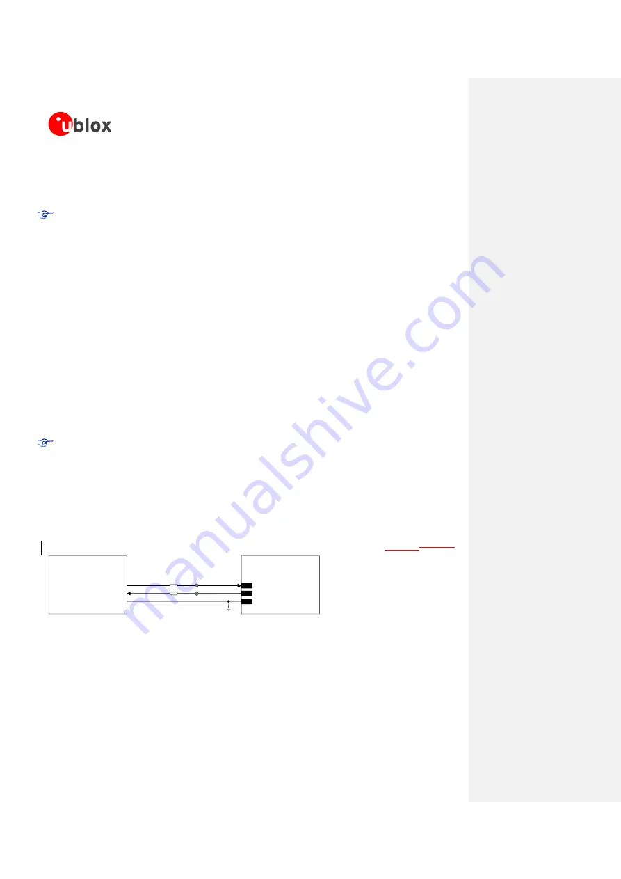
The circuit with a 1.8 V Application Processor should be implemented as described in
TxD
Application Processor
(1.8V DTE)
RxD
SARA-G3 series
(1.8V DCE)
29
TXD_AUX
28
RXD_AUX
GND
GND
0 ohm
0 ohm
TestPoint
TestPoint
Figure 53: UART AUX interface application circuit connecting a 1.8 V application processor


