


SARA-G3 series - System Integration Manual
UBX-13000995 - R06
Objective Specification
System description
Page 52 of 218
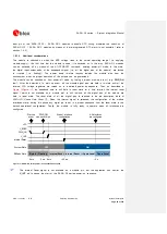
CTS signal behavior
The module hardware flow control output (
CTS
line) is set to the ON state (low level) at UART
initialization.
If the hardware flow control is enabled, the
CTS
line indicates when the UART interface is enabled (data
can be sent and received). The module drives the
CTS
line to the ON state or to the OFF state when
it is either able or not able to accept data from the DTE.
Refer to section 1.9.1.4 for the complete description. For more details, refer to
u-blox AT Commands
Manual [2], AT&K, AT\Q, AT+IFC AT command.
If the hardware flow control is not enabled, the
CTS
line is always held in the ON state after UART
initialization.
If hardware flow control is enabled, then when the
CTS
line is ON the UART is enabled and the
module is in active-mode. If the
CTS
line is OFF it does not necessarily mean that the module is
in idle-mode, but only that the UART is not enabled (the module could be forced to stay in
active-mode for other activities, e.g. network related).
When the power saving configuration is enabled and the hardware flow-control is not implemented in
the DTE/DCE connection, data sent by the DTE can be lost: the first character sent when the
module is in idle-mode will not be a valid communication character (see section 1.9.1.4 for
complete description).
When the multiplexer protocol is active, the
CTS
line state is mapped to FCon / FCoff MUX
command for flow control issues outside the power saving configuration while the physical
CTS
line
is still used as a power state indicator. For more details, refer to
Mux Implementation Application
Note [20].
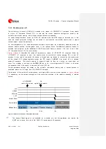
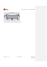
RTS signal behavior
The hardware flow control input (
RTS
line) is set by default to the OFF state (high level) at UART
initialization. The module then holds the
RTS
line in the OFF state if the line is not activated by the
DTE: an active pull-up is enabled inside the module on the
RTS
input.
If the HW flow control is enabled (for more details, refer to
u-blox AT Commands Manual [2] AT&K,
AT\Q, AT+IFC command descriptions) the module monitors the
RTS
line to detect permission from the
DTE to send data to the DTE itself. If the
RTS
line is set to the OFF state, any on-going data
transmission from the module is immediately interrupted or any subsequent transmission forbidden until the
RTS
line changes to the ON state.
The DTE must still be able to accept a certain number of characters after the
RTS
line is set to
the OFF state: the module guarantees the transmission interruption within two characters from
RTS
state change.
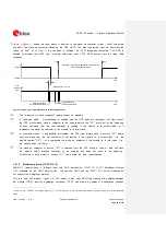
If AT+UPSV=2 is set and HW flow control is disabled, the module monitors the
RTS
line to manage the
power saving configuration:
When an OFF-to-ON transition occurs on the
RTS
input line, the UART is enabled and the module
is forced to active-mode; after ~20 ms from the transition the switch is completed and data can be


