


SARA-G3 series - System Integration Manual
UBX-13000995 - R06
Objective Specification
Product Testing
Page 186 of 218
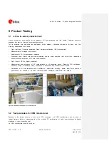
Module assembly on the device; it should be verified that:
o
Soldering and handling process did not damaged the module components
o
All module pins are well soldered on device board
o
There are no short circuits between pins
Component assembly on the device; it should be verified that:
o
Communication with host controller can be established
o
The interfaces between module and device are working
o
Overall RF performance test of the device including antenna
Dedicated tests can be implemented to check the device. For example, the measurement of module current
consumption when set in a specified status can detect a short circuit if compared with a “Golden Device”
result.
Module AT commands are used to perform functional tests (communication with host controller, check SIM
card interface, check communication between module and GNSS, GPIOs, etc.) and to perform RF
performance tests.
5.2.1
“Go/No go” tests for integrated devices
A ‘Go/No go’ test is to compare the signal quality with a “Golden Device” in a position with excellent
network coverage and after having dialed a call (refer to
u-blox AT Commands Manual [2], AT+CSQ
command: <rssi>, <ber> parameters).
These kinds of test may be useful as a ‘go/no go’ test but not for RF performance measurements.
This test is suitable to check the communication with host controller and SIM card, the audio and power
supply functionality and verify if components at antenna interface are well soldered.
5.2.2
Functional tests providing RF operation
Overall RF performance test of the device including antenna can be performed with basic instruments such
as a spectrum analyzer (or an RF power meter) and a signal generator using AT+UTEST command over
AT interface.
The AT+UTEST command gives a simple interface to set the module to Rx and Tx test modes ignoring
GSM/GPRS signaling protocol. The command can set the module:
In transmitting mode in a specified channel and power level in all supported modulation schemes
(single slot GMSK) and bands
In receiving mode in a specified channel to returns the measured power level in all supported bands
Refer to the
u-blox AT Commands Manual [2], for AT+UTEST command syntax description.
Refer to the
End user test Application Note [23], for AT+UTEST command user guide, limitations
and examples of use.


