


SARA-G3 series - System Integration Manual
UBX-13000995 - R06
Objective Specification
Design-in
Page 132 of 218
Reference
Description
Part Number - Manufacturer
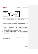
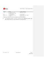
C1, C2
100 nF Capacitor Ceramic X7R 0402 10% 16 V
GRM155R61A104KA01 - Murata
U1
Unidirectional Voltage Translator
SN74AVC4T774 - Texas Instruments
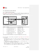
Table 28: Component for UART application circuit with partial V.24 link (5-wire) in DTE/DCE serial communication (3.0 V DTE)
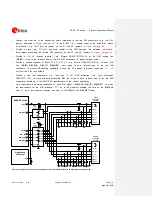
If only
TXD
,
RXD
,
RTS
and
CTS
lines are provided, as implemented in
, the procedure to enable power saving depends on the HW flow-control status. If HW
flow-control is enabled (AT&K3, that is the default setting) power saving will be activated by
AT+UPSV=1. Through this configuration, when the module is in idle-mode, data transmitted by the DTE is
buffered by the DTE and is correctly received by the module when active-mode is entered.
If the HW flow-control is disabled (AT&K0), AT+UPSV=2 can enable the power saving. The module is
in idle-mode until a high-to-low (i.e. OFF-to-ON) transition on the
RTS
input line switches the module
from idle-mode to active-mode in 20 ms. The module is forced into active-mode if the
RTS
input line is
held in the ON state.
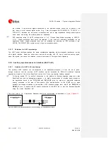
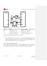
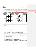
Providing the TXD and RXD lines only (not using the complete V24 link)
If the functionality of the
CTS
,
RTS
,
DSR
,
DCD
,
RI
and
DTR
lines is not required in the application, or
the lines are not available, the circuit with a 1.8 V Application Processor should be implemented as
described in
Connect the module
RTS
input line to GND or to the
CTS
output line of the module: since the
module requires
RTS
active (low electrical level) if HW flow-control is enabled (AT&K3, that is the
default setting), the pin can be connected using a 0
series resistor to GND or to the active-
module
CTS
(low electrical level) when the module is in active-mode, the UART interface is enabled
and the HW flow-control is enabled
Connect the module
DTR
input line to GND, since the module requires
DTR
active (low electrical
level)
Leave
DSR
,
DCD
and
RI
lines of the module unconnected and floating
TxD
Application Processor
(1.8V DTE)
RxD
RTS
CTS
DTR
DSR
RI
DCD
GND
SARA-G3 series
(1.8V DCE)
12
TXD
9
DTR
13
RXD
10
RTS
11
CTS
6
DSR
7
RI
8
DCD
GND
Figure 51: UART interface application circuit with partial V.24 link (3-wire) in the DTE/DCE serial communication (1.8V DTE)


