background image

C2-1000 S

ERIES 

O

PERATION

M

ANUAL

78

13.3

Application menu’s

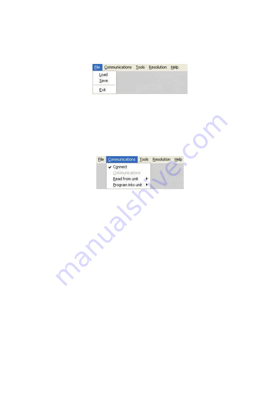
13.3.1 File menu

Figure 6 File menu

Across the top of the application are the toolbar menu options.  The first menu item 
is 

File

within this menu you can 

Save

and 

Load

previous setups into the application, 

these setups contain all the settings of the unit.  Following a Load the application will 
ask if you would like to synchronize the unit, if you do not synchronize then the unit 
and the application will show different values.

13.3.2 Communications menu

Figure 7 Communications menu

The communications menu provides the 

Connect

item which provides a means to 

disconnect from the unit and return to the main screen.  

Read from unit

is very 

important as it allows selective or all of the settings to be read from the unit. 
Depending on your unit some of the following 

Read from unit 

menu items are not 

available.  

-

The 

Read All

option will read each of the setting sections from the unit and 

update the application.  This item should be selected following connecting to a 
unit as it will synchronize the unit and the application.

-

The 

Read Macros

will read the macros that are stored within the unit. 

-

The 

Read Buttons

will read the button assignments from the unit and update 

the buttons and the buttons tab within the application.

-

The 

Read Resolutions

will read the complete resolution database that is 

currently stored in the unit.  This step must be performed in order to select 
resolutions by name and to be able to edit resolutions.

-

The 

Read Parameters

will read the all of the adjustments from the unit and 

update the applications. 

-

The last menu available in Communications is 

Program into unit

this allows 

selective or all the settings to be programmed into the unit.

-

The 

Program All

menu will program each of the settings sections into the 

scaler.

-

The 

Program Macros

menu will program only previously read or loaded 

macros into the unit.

Summary of Contents for C2-1000 Series

Page 1: ...C2 1000 Series Video Processor Operation Manual...

Page 2: ...C2 1000 SERIES OPERATION MANUAL...

Page 3: ...Switching units between different resolutions NTSC PAL and Default 18 5 3 4 Forcing NTSC output resolution 18 5 3 5 Forcing PAL output resolution 18 5 3 6 Forcing default output resolution 18 6 AUDIO...

Page 4: ...CONTROL SPECIFICATION 48 10 1 Communication protocol basics 48 10 2 Packet format 49 10 3 Function list 51 10 4 Examples 58 10 5 Reading and writing macros 58 10 5 1 Reading a previously stored Macro...

Page 5: ...solution Editor 83 14 TROUBLESHOOTING AND TECHNICAL SUPPORT 87 14 1 There is no picture on the Output 87 14 2 The image is shifted and not fully viewable 87 14 3 The output resolutions no longer appea...

Page 6: ...5 18 1 Video Inputs 95 18 2 Computer Input 95 18 3 Video Outputs not present on all units 95 18 4 Computer Outputs 95 18 5 Audio input output certain models only 96 18 6 Locking Mixing 96 18 7 Scaling...

Page 7: ...nd exclusive liability to the supplier and manufacturer regardless of the form of action shall not exceed the replacement cost of the materials described herein By using this equipment you have indica...

Page 8: ...or describes the proper connection of this equipment for operation that insures FCC compliance Direct all inquiries regarding FCC compliance to TV One Multimedia Solutions 1350 Jamike Drive Erlanger...

Page 9: ...cord is disconnected from the wall outlet The AC wall outlet should be installed near to the unit and be easily accessible Do not plug in or attempt to operate an obviously damaged unit 2 2 Water and...

Page 10: ...operation avoid obstruction of these openings and ensure the unit is installed in a well ventilated area 2 6 Intellectual property Some IC chips in this product include confidential and or trade secr...

Page 11: ...longue p riode assurez vous que le c ble d alimentation lectrique est d connect de la prise murale La prise murale de courant doit tre install e pr s de l unit et ais ment accessible Ne branchez pas e...

Page 12: ...s sur les cot s de l unit servent l a rer Pour permettre une utilisation s re vitez d obstruer ces ouvertures et assurez vous que l unit est install e dans un endroit bien a r 2 6 Propri t intellectue...

Page 13: ...de desconectar el cable de corriente CA de la toma de la pared cuando no va a utilizar el aparato por un periodo largo de tiempo La toma CA de la pared ha de estar instalada cerca del aparato y debe...

Page 14: ...ntilaci n Para asegurar una operaci n eficaz se debe evitar la obstrucci n de estos agujeros y tambi n asegurar que el aparato se instale en una zona con adecuada ventilaci n 2 6 Propiedad intelectual...

Page 15: ...t ziehen Sie bitte das Stromkabel aus der Steckdose Die Steckdose sollte sich in der N he des Ger ts befinden und leicht zug nglich sein Verbinden Sie ein offensichtlich besch digtes Ger t keinesfalls...

Page 16: ...s Um die ordnungsgem e Bel ftung zu gew hrleisten d rfen diese ffnungen nicht verdeckt werden Sorgen Sie au erdem daf r dass das Ger t an einem gut bel fteten Ort aufgestellt wird 2 6 Gewerbliches eig...

Page 17: ...re tijd niet gebruikt zorg er dan voor dat de stekker van het wisselstroomsnoer uit het stopcontact is getrokken Het wisselstroom stopcontact moet dichtbij de eenheid ge nstalleerd worden en makkelijk...

Page 18: ...euven en openingen aan de zijkant van de eenheid zijn voor ventilatie Zorg er voor dat de eenheid op een goed geventileerde plek ge nstalleerd wordt zodat deze betrouwbaar werkt 2 6 Intellectueel eige...

Page 19: ...is inputted to the unit The input signal is then converted into a suitable signal which can then be displayed for use on a video screen or television such as composite video Down Converter PLUS This...

Page 20: ...tored in individual non volatile memories for retrieval once the unit s power has been removed The Video Scaler units employ pixel adaptive motion compensation to de interlace fast moving images and a...

Page 21: ...L 15 4 PRODUCT IMAGES Your C2 1000 product should look like one of the units below Each unit has a different main function Down Converter Video Scaler Universal Scaler and a subsequently different abi...

Page 22: ...switch Press once to show the on screen display OSD Hold in to cancel the OSD Press and hold in to store current settings into memory They will then be restored on power on or when RESTORE is pressed...

Page 23: ...menu structure or change a parameter and are detailed in a later section 5 3 Special button combinations and functions In addition to the ability to perform a factory reset and forcing certain output...

Page 24: ...n the following methods below can be used When you are happy with the output resolution selected press and hold the multi directional switch in to store the current settings Please note that these cha...

Page 25: ...See Adjust sources for more information on manually selecting an input type On some units such as Video Scalers the PC HD input is there just to loop the PC image through to the PC monitor in bypass m...

Page 26: ...er over up to 300 meters of UTP cable 6 3 Audio inputs and outputs Certain models C2 1200 C2 1250 C2 1350 support audio switching simultaneous with video switching This means that audio input 1 might...

Page 27: ...rough Adjusts current the menu structure menu values changes values Left right alter current value and Toggles between up down alter the zoom pan mode next value Toggles freeze Selects the next on and...

Page 28: ...ue will begin to flash Change the value by moving the switch left or right Then finalise your adjustment by pressing the multi directional switch once more A few menu items have multiple parameters wi...

Page 29: ...those shown The SW number refers to the version of firmware loaded into the unit this can be upgraded from the support website The PT and BT numbers refer to Hardware version information and are of i...

Page 30: ...ssing delay and the background for the output will be that of the Lock source unless foreground and background are swapped In both Genlock and Lock Mix modes the source selected for the lock input det...

Page 31: ...units with an SDI output and when locking to a CV or YC input An internal de jitter circuit ensures that the SDI output has a low jitter over the full 10Hz to 100kHz range even though the CV or YC in...

Page 32: ...ailed description of the other modes This menu item only appears on units with multiple windows or PIPs It is used to select which one you want to modify Alternatively use one of the dedicated buttons...

Page 33: ...top bottom or sides By adjusting the H V values you can crop out the black areas to correct the size on the final output screen Note that it does not change the shape or aspect ratio of the image but...

Page 34: ...ther details on this item This is a feature only present in advanced units only It greatly improves the method of frame rate conversion by allowing the unit to merge frames together during the process...

Page 35: ...nt Note This menu item only appears on multi channel scalers This adjustment selects the order of the window layers Layers are shown for a and b logo screens Window A Window B and Z is the Lock Source...

Page 36: ...automatically calculated for you based on the incoming resolution and the H V Zoom values Most resolutions are 4 3 ratio thus the third number will be 1 333 4 divided by 3 Another common aspect ratio...

Page 37: ...caled to the required output of size 250 x 300 8 5 Items Associated with the Adjust keyers group Please note that not all units have this sub menu it is only present on units with overlaying abilities...

Page 38: ...oreground keyed Background non keyed Output resolution XGA NTSC Off XGA NTSC NTSC XGA NTSC On NTSC XGA NTSC NTSC XGA Off NTSC XGA XGA NTSC XGA On XGA NTSC XGA XGA is 1024x768 You will see that the Swa...

Page 39: ...thin the Adjust keyers group Please also see the section titled EDGE BLENDING SETUP later in this manual This menu item controls which of the 4 edges are blending into the background In general only t...

Page 40: ...adjusted to correct for corner brightness errors 8 7 Items Associated with the Adjust sources group The Adjust Sources menu group accesses the parameters associated with the processing amplifiers use...

Page 41: ...s is only functional for certain units with built in audio switching or when used with an optional Audio Switcher not all units support this function In most situations the Audio input values would be...

Page 42: ...interlacing of an image The following options are available for this menu item Mode Function Normal The two interlaced fields are simply combined together This will often show artifacts on moving imag...

Page 43: ...l preferably with very sharp vertical lines Adjust this value until you see the sharpest image Alternately adjust this value to give the worst noisiest softest image and then add or subtract 16 to get...

Page 44: ...0 being the default Note that over enhancing an image has the side effect of making it appear to be noisy and under enhancing an image gives the appearance of poor video quality On occasion a video s...

Page 45: ...rols how long a transition from one input to another takes The value can be 0 a cut or several minutes adjustable in 1 10th second increments If you selected Wipe or Push for the transition type then...

Page 46: ...t is not displayable on a monitor The resolutions and values within the database are industry standards and should not normally be altered by the user That said there might be times when it is necessa...

Page 47: ...monitors will display an image with an odd moir effect such as soft vertical bands spread evenly across the image This menu controls the total number of lines of video present in the image which inclu...

Page 48: ...tion of the image begins Do not attempt this adjustment without monitoring the results with an oscilloscope There are standards for all current computer and broadcast resolutions that specify the corr...

Page 49: ...owever both designators are important to support personnel This is an information page showing when the currently installed software was released The information is useful to the user as he or she com...

Page 50: ...ium is the default level which is recommended for normal use Windows type images etc This parameter controls whether the welcome screen is displayed or not on power up for units with an on screen disp...

Page 51: ...ay increase the total number of resolutions defined in the database If your units supports Logos or Testcards then this screen will display how many are present in the memory of the units Power Cycles...

Page 52: ...the ambient temperature at four locations within the case and can be an early predictor of a shutdown before the shutdown actually occurs Should you experience problems with your unit Technical Suppo...

Page 53: ...eed be 9 2 Communications protocol The standard communications protocol for your unit is text based and is detailed on our website Also on our website you can find the Windows Control Panel for your u...

Page 54: ...hereby provided software handshaking Note that a line feed LF should not be sent It may take around 30ms 0 03 seconds for an RS232 command to be actioned and acknowledged this will vary between differ...

Page 55: ...etc If absolutely required to simplify programming the user may send packets one after the other with around 100ms 100 milliseconds between each one However this will not work for all packets such as...

Page 56: ...7 0 Reserved Bit 6 0 Represents the window to be adjusted for multi channel units only E g Window A the default for single channel units is sent as 41 since 0x41 is ASCII for A 0x61 is ASCII for a a L...

Page 57: ...ure is not supported on Function codes are given in hexadecimal and adjustment range is in decimal but always sent as hexadecimal For dual channel units the mode of operation also restricts what Windo...

Page 58: ...0 RGBHV 3 YUV 9 Not available Background Y 13B 16 235 Background U 13C 16 240 Background V 13D 16 240 SDI optimization 197 0 1 Off On Output Standard 101 0 NTSC PAL 1 PAL M PAL N 2 SECAM Output CV YC...

Page 59: ...Enable 12B 0 1 Off On Zoom level 086 100 1000 Zoom level H 103 100 1000 only used in Advanced A R mode Zoom level V 105 100 1000 only used in Advanced A R mode Aspect ratio in 107 0 1 1 9 99 1 read o...

Page 60: ...nvert 122 0 1 Off On U key min max min 0B0 0 255 U key min max max 0B3 0 255 U key Softness 123 0 255 U key Invert 124 0 1 Off On V key min max min 0B1 0 255 V key min max max 0B4 0 255 V key Softness...

Page 61: ...stcard F0 F1 0DC 0 10 Autoset 10 1F 0FE 1 Start Autoset procedure TL pos adj left 10 FF 0B6 100 100 TL pos adj top 10 FF 0B7 100 100 BR size adj right 10 5F 0DE 100 100 BR size adj bottom 10 5F 0DF 10...

Page 62: ...07 SDI1 1 to SD1 8 0x08 to 0x0F SDI2 1 to SDI2 8 0x10 to 0x1F AES1 to AES16 Volume trim 205 128 to 127 Delay adjust 204 100 to 5000 Adjust transitions on certain models only Transition type 112 0 3 Cu...

Page 63: ...1 to store Buzzer 0CB 0 1 Off On CC 300 A B bus enable 202 0 1 Off On Power cycles 0D6 Read only Firmware updates 0DD Read only Hours in use 0D7 Read only Resolutions 0D8 Read only Number of Testcard...

Page 64: ...44 00 41 00 87 000064 70 CR Read 1C Zoom level invalid as window C does not exist F 84 00 43 00 86 CR F 04 00 43 00 86 000000 CD CR Read 1B Zoom level Zoom 100 F 84 00 42 00 86 CR F 44 00 42 00 86 000...

Page 65: ...Read the Data for the first item in the preset macro Payload is the data for the function 100 F 84 01 42 00 F2 B9 CR F 44 01 42 00 F2 000064 5D CR Read the Function for the second item in the preset m...

Page 66: ...00 F2 000011 02 CR Write the data for the second item 100 F 04 02 42 00 F2 000064 9E CR F 44 02 42 00 F3 000011 DE CR 10 5 3 Run and Restore macros Macros once programmed can be run by sending one of...

Page 67: ...grey or white then its value is 128 being the mid point 11 1 1 Preparation 1 Enter the Adjust windows menu 2 Select the Source this will be the foreground 3 Exit the Adjust windows menu 4 Enter the A...

Page 68: ...C2 1000 SERIES OPERATION MANUAL 62 to decrease the min values and increase the max values to broaden the range of colors keyed out At this point only the key color should remain transparent...

Page 69: ...suitable number of TV One s CORIO 2 scaling engines The C2 7000 series are dual processors and therefore require only a single unit to perform both tasks whereas other units will generally require tw...

Page 70: ...will be vital 4 Adjustable mountings or more preferably projectors with built in advanced adjustments Proper alignment of two projectors can be very difficult but will be aided by using some sort of...

Page 71: ...jectors are already fixed into position check that there is around 10 to 20 overlap or edge blending will not be possible You must also ensure that both projects are in focus with the same zoom settin...

Page 72: ...deo source is split into 2 signals or use the loop output available on some units 12 5 Initial setup This section describes how to start setting your scaler up It is vital that your scaler is clean of...

Page 73: ...90 with H pan of 100 fully right If your projectors are properly setup and connected with the scaler active with the above settings you should now have a very rough overlap of the two images on a sing...

Page 74: ...160 190 1920 x 1080i 192 To set these edge blend widths perform the following 1 Go into the Adjust keyers menu 2 For Output 1 1A change E blnd size the first number to the H size recommended above 3 F...

Page 75: ...s so that the above mentioned red and green vertical lines perfectly overlap to produce yellow ones Depending on how your projectors are aligned you ll get different results each with different soluti...

Page 76: ...o re align them Key stoning ensure your projectors have the same keystone values to produce perfectly aligned vertical lines G R R G RG G R Offset make sure your projectors are perfectly aligned both...

Page 77: ...number to the same gamma value as per above 4 Repeat steps 2 and 3 changing up or down as necessary until the bright patch has disappeared The 2nd number in the E blnd gamma is for where you have proj...

Page 78: ...also be necessary to change your vertical zoom value differently to the horizontal one This is best done after projector alignment by performing the following 1 Go to the Adjust windows menu and chang...

Page 79: ...he 190 zoom factor Other setup approaches are also used where the zoom factor is adjusted to the projectors current position for instance if they are already fixed into their final positions Assuming...

Page 80: ...1 185 188 188 190 192 160 175 180 184 188 188 190 192 165 174 179 184 187 187 190 191 170 173 179 183 187 187 189 191 175 173 178 183 186 186 189 191 180 172 178 182 186 186 189 191 185 171 177 182 18...

Page 81: ...the communications method that the application will use 13 1 1 Selecting a serial port connection Select the Communications item from the Communications toolbar Then click the Serial option on the po...

Page 82: ...be unique 13 2 Connecting to a unit This main screen allows you to operate the application in one of two modes firstly Demo mode which allows you to familiarize yourself with the unit control without...

Page 83: ...to a unit you will be asked if you wish to synchronize with the unit this will read all the settings from the connected unit and update the application Figure 5 Synchronize application Once synchroniz...

Page 84: ...tems are not available The Read All option will read each of the setting sections from the unit and update the application This item should be selected following connecting to a unit as it will synchr...

Page 85: ...y to program Logos and Testcards into the unit The source image can be in JPG BMP or GIF format which is then compressed and downloaded to the unit For Logos the Image Loader provides the ability to s...

Page 86: ...g the required operations to the correct Define Button section As can be seen in the example above for Button2 we have multiple actions which are cycling sources and then waiting for 2000 milliseconds...

Page 87: ...slots available depending on the unit type Pressing program will convert the image into its raw RGB values and then compress it if the image is too large once compressed then the programming sequence...

Page 88: ...ge is too large once compressed then the programming sequence will stop and report that the image is too large complex To key part of the image select the Keyer checkbox You can now use the mouse righ...

Page 89: ...le If we take a single line of pixels and look at them closely we will see for a non aliased image solid pixels of one colour If we look at a line when anti aliased we can see that no longer is the le...

Page 90: ...Timing Formula GTF in order to make the created resolutions as compatible as possible with standard video equipment If you find your created resolution does not work effectively try the calculation u...

Page 91: ...s currently in the scaler The second method of creating a resolution requires you to know all the detailed timing parameters The timings tab allows all the detailed video timing information to be adde...

Page 92: ...on simply click on the resolution table at the bottom of the screen and it parameters will be editable within the Timings tab Once the edits are complete click on Update to modify the settings for the...

Page 93: ...and the display equipment Check that the display video equipment is set to the correct line input and format standard as appropriate Check that the device connected to the output is on and can support...

Page 94: ...it If you cannot achieve exactly what you desire then alter the inputs levels in Adjust sources until the correct colors are restored 14 7 How can I reduce color smearing on CV connections Smearing us...

Page 95: ...ethod is set correctly Having YUV input selected instead of RGBHV often causes this problem 14 12 The video signal from my DVD player does not appear to work Some DVD players have a switch at the back...

Page 96: ...gged in and are not damaged and then make certain that all equipment connected to the unit is working properly Perhaps you have a frozen unit and you cannot change an input nor exit from the current t...

Page 97: ...kaging and on any accompanying documentation This will greatly speed up processing IMPORTANT DO NOT return a unit for warranty repair without first obtaining a Return Authorization Number No action wi...

Page 98: ...fic warranties are available upon request to TV One If repairs are necessary under this warranty policy the original purchaser must obtain a Return Authorization Number from TV One and return the prod...

Page 99: ...ut pulled high on output used for auto termination 12 SDA input output linked 13 H sync or composite sync for RGBS 14 V sync 15 SCL input output linked 17 2 RS232 D9 socket 1 N C 2 TX Transmit data 3...

Page 100: ...000 SERIES OPERATION MANUAL 94 17 4 Multi way audio connector L Left signal G Signal ground shared with left and right R Right signal 17 5 UTP output 1 Red 2 Red 3 N C 4 Green 5 Green 6 N C 7 Blue 8 B...

Page 101: ...250Hz for PAL Operation 18 2 Computer Input Analog RGB YPbPr via HD15 into 75 Ohm supporting RGBHV RGBS RGsB YPbPr auto terminating into 75 Ohm Digital sync in RGBHV or RGBS mode TTL Level 10K termin...

Page 102: ...rlay one CV or YC source over a different CV or YC source or one RGB YUV source over another RGB YUV source you are restricted to overlaying CV YC over RGB YUV or RGB YUV over CV YC the exception is w...

Page 103: ...5mm locking center pin positive DC power connector A non locking 2 5mm DC power connector will also fit 18 12 Control Methods The unit can be controlled locally via the front panel buttons multi dire...

Page 104: ...www tvone com www tvone eu TV One Asia TV One China 11F No 28 Sec 2 Rm 9C Neiwailian Building San Min Road Panchiao City No 518 Shangcheng Road Taipei Hsien 220 Pudong Shanghai Taiwan ROC China 200120...

Reviews: