30
9. MODEL 4000C AND 5500C SERIES DISASSEMBLY AND REASSEMBLY
WARNING
Before performing any repair or replacement, disconnect and lock out
power.
With proper maintenance and lubrication, normal life expectancy for gears, bearings, and seals can be
achieved. However, over a period of time these parts must be replaced to maintain the efficiency of your
booster. This section is written in a way that will allow you to completely disassemble your booster. The
inspection of certain repairable or replaceable parts is referred to at the point of disassembly where these
parts are exposed. If at any point of inspection, repair or replacement is deemed necessary, appropriate
instruction will be given to achieve these repairs or replacements is deemed necessary, appropriate
instruction will be given to achieve these repairs or replacements.
9.1 DISASSEMBLY OF 4000C AND 5500C SERIES BOOSTERS
1. Disconnect cooling water
lines [274 & 181]. Do not
disturb the large hex head
screw [97]. If it is removed,
loosened, or water is
detected in drain oil, the
coil assembly must be
retested as described in the
assembly procedure.
2. Drain oil from both ends of
booster and remove port
fittings [38 or 48].
3. Remove bolts [93] and take
off seal housing [91] using jack screws.
4. Remove cover [6], mating ring [76] will come off with cover.
5. Remove drive shaft screws [66] and locks [65]. Tap shaft lightly to remove.
6. Remove gear lock nuts and washers [35 & 36].
Model 5500 - 91/93 series
(top drive only). Remove cap screw [396] washers [136 & 80] and oil
slinger [20] if furnished.
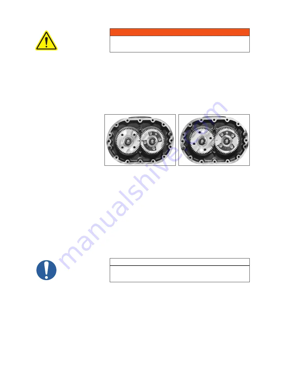
7. Position the timing gears for pulling by first matching the timing marks on the gears. See Figure 11. Turn
the drive gear clockwise five teeth and mark a matching reference line on each gear as shown in Figure
12, above. The rotor lobes are now in their most open position. Using a gear puller, the driven gear (left
hand helix) may now be removed without jamming the rotors. This gear is in two parts - the gear rim and
hub. It is not necessary to disassemble. Do not allow the gears to move from the matched reference line
while pulling. Use a light rocking motion while pulling the gear to insure that the lobes have not jammed.
NOTE
Failure to properly pull this gear could result in damage to rotor keyway or
a bent rotor shaft. Never use excessive force.
8. Remove drive gear. It is not necessary to remove keys from rotor shafts.
9. Remove cap screw [62], locks [61], and bearing lock rings [14].
10. Install two screws temporarily to hold end plate to housing.
11. Remove the free end cover [7], rotor shaft socket screws [26 & 69], washer [25], spacer [57], oil slinger
[21] (must be pried off on model 5500), roll or dowel pin [68], socket head screws [30], and oil retainer
rings [14 or 15].
Figure 11 - Position of timing marks
Keyways in line
and timing marks matched
Figure 12 - Position of timing marks
Timing marks advanced 3 teeth and
reference marks aligned.
Summary of Contents for M-D Pneumatics 7010
Page 43: ...43 NOTES ...
Page 50: ...50 3200C CUTAWAY DRAWING 3200 90C 91C 92C 93C 1 OF 2 A ...
Page 51: ...51 3200C CONFIGURATIONS DRAWINGS 3200 90C 91C 92C 93C 2 of 2 A ...
Page 54: ...54 5500C CUTAWAY DRAWING 5500 90C 91C 92C 93C 1 OF 2 E OIL LEVEL SIGHT GAUGE DETAIL ...
Page 55: ...55 5500C CONFIGURATIONS DRAWINGS 5500 90C 91C 92C 93C 2 of 2 E ...
Page 56: ...56 7000C CUTAWAY DRAWING 7000 90C 91C 1 OF 3 ...
Page 57: ...57 7000C CONFIGURATIONS DRAWING 7000 90C 2 OF 3 ...
Page 58: ...58 7000C CONFIGURATIONS DRAWING 7000 91C 3 OF 3 7000 91C 7013 SHOWN ...
Page 68: ...68 NOTES ...


