26
7. Mark housing, end plates, rotors, and gears before proceeding with disassembly. There are two methods
which can be used to disassemble the rest of the unit. Method “A” requires an arbor press and method
“B” requires the use of bar or yoke pullers. See puller drawing (T29603) on page 44.
8.
Method A:
a. Place two support blocks, 5-1/2 to 6 inches (14 to 15.5 cm) high (hard wood or steel), on the bed
of an arbor press. Set the unit, with the gears pointing down, on the two blocks making sure the
blocks support the rotor housing only. Press both rotors out of free end bearings simultaneously.
NOTE
Failure to properly pull this gear could result in damage to rotor keyway or
a bent rotor shaft. Never use excessive force.
b. Lift the housing off the rotors and remove the non-drive end plate [4] by tapping the end plate from
the inside of the housing. Place the rotor housing back over the rotors.
c. Set the unit on the support blocks with the gears pointing upward. Do not extend blocks into the
rotor bores. The rotors may now be pressed from the gear end plate. Do not damage rotors.
Method B:
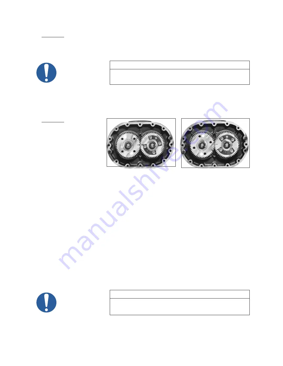
a. Align timing marks on
gears (Figure 7). Rotate
drive gear clockwise
approximately three
teeth and mark a
matching reference line
on each gear as shown
in Figure 8. This gear
position is necessary so
rotors will clear and not
jam. Do not allow the
gears to move from the
matched reference line while pulling. Use a light rocking motion to insure that the lobes have not
jammed. Remove driven gear first then drive gear.
b. Remove button head Allen screws [30] and bearing retainer rings [14] from both end plates.
c. Attach a pair of bar pullers to the bearing bores of the free end plate. Use 10-32 × 4” long screws (no
metric equivalent) Alternately push both rotors from end plate. Separate end plate from housing.
d. Turn the unit around and attach a single bar puller to either bore and push rotor from end plate
making sure the rotor is vertical in the housing (for support) while removing. Repeat for opposite
rotor. Note location of timing shims [16], oil slinger [20], and spacers [17 & 18].
e. Tap end plate from housing.
9.
90/91 Series
- Tap out bearings from both end plates. Note location of spacers under bearings and
retain for reassembly. To remove seals [54] use a cape chisel or similar tool being careful not to nick
or cut the bearing or seal bores. Remove the labyrinth seal [51] in the same manner. The seals will be
damaged by removal and must be replaced.
92/93 Series
- Carefully tap out seal slinger [238], spacer [123], and bearings. The oil slinger stator
[79] should not be removed unless it is damaged or the end plate is to be replaced.
NOTE
On some older units the oil seal slinger is made up of two separate parts,
items 238 & 129. The newer design combines these two parts and is
identified as item 238.
10. Clean all parts with good grade of clean solvent and replace any worn or damaged parts with factory
approved parts. New bearings, seals, and O-rings should be installed at each assembly.
Figure 7 - Position of timing marks
Keyways in line
and timing marks matched
Figure 8 - Position of timing marks
Timing marks advanced 3 teeth and
reference marks aligned.
Summary of Contents for M-D Pneumatics 7010
Page 43: ...43 NOTES ...
Page 50: ...50 3200C CUTAWAY DRAWING 3200 90C 91C 92C 93C 1 OF 2 A ...
Page 51: ...51 3200C CONFIGURATIONS DRAWINGS 3200 90C 91C 92C 93C 2 of 2 A ...
Page 54: ...54 5500C CUTAWAY DRAWING 5500 90C 91C 92C 93C 1 OF 2 E OIL LEVEL SIGHT GAUGE DETAIL ...
Page 55: ...55 5500C CONFIGURATIONS DRAWINGS 5500 90C 91C 92C 93C 2 of 2 E ...
Page 56: ...56 7000C CUTAWAY DRAWING 7000 90C 91C 1 OF 3 ...
Page 57: ...57 7000C CONFIGURATIONS DRAWING 7000 90C 2 OF 3 ...
Page 58: ...58 7000C CONFIGURATIONS DRAWING 7000 91C 3 OF 3 7000 91C 7013 SHOWN ...
Page 68: ...68 NOTES ...


