background image

Operating Spanner Modules at Modbus TCP

Hans Turck GmbH & Co. KG | T +49 208 4952-0 | F +49 208 4952-264 | [email protected] | www.turck.com

40

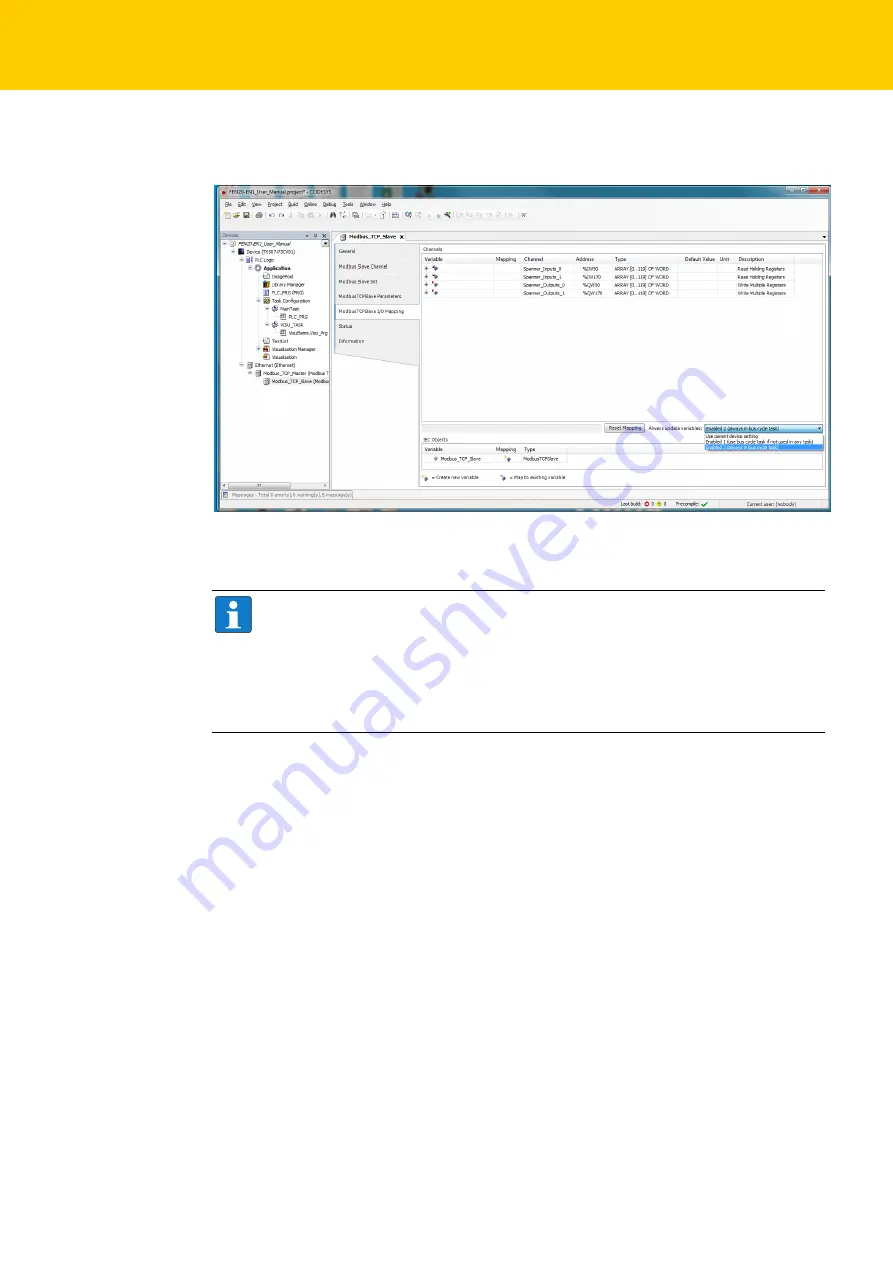
In the ”Modbus TCP Slave I/O Mapping” tab, change the value of the “Always Update Variables” 
drop down box to “Enabled 2 (Always in Bus Cycle)”. 

 Click “Online” 

 “Login” and download the program to the TX507. 

Follow the prompts.

Fig. 34: CODESYS – update variables

NOTE

If the PLC supports the function, it is reasonable to use Function Code FC23 
„read/write multiple register“ in order to read or write all of the 240 data words in one 
channel. The read-write access should start at the beginning of the data segment to be 
read or written in order to guarantee a consistent data transmission between PLCs. It is up 
to the user to test data transfer consistency when multiple blocks of I/O data are read from 
and written to a single spanner port. 

Summary of Contents for 6814035

Page 1: ...Your Global Automation Partner TBEN L EN1 FEN20 EN1 Spanner Modules Getting Started Guide ...

Page 2: ...2 Hans Turck GmbH Co KG T 49 208 4952 0 F 49 208 4952 264 more turck com www turck com ...

Page 3: ... FEN20 EN1 15 5 Address Setting for Spanner Modules 17 5 1 Address setting at TBEN L EN1 17 5 2 Address Setting at FEN20 EN1 21 5 3 Assign the IP Address with Turck Service Tool Port 1 only 21 6 The Web Server 23 6 1 Security in the Web Server 23 6 2 Address Setting via the Web Server 23 6 3 Web Server and Spanner Data Mapping 27 6 3 1 Spanner Data Mapping 27 6 3 2 Modbus TCP Status and Input Data...

Page 4: ...ameters 33 7 3 5 Error behavior watchdog 33 7 4 Mapping the FEN20 EN1 into a CODESYS V3 Project 34 8 Operating Spanner Modules at EtherNet IP 45 8 1 EtherNet IP Standard Classes 45 8 2 Ethernet IP EN1 Process Data Mapping 45 8 3 Mapping the FEN20 EN1 into a RSLogix project Ethernet IP Generic Device 46 9 Operating Spanner Modules at PROFINET Port 2 only 55 9 1 PROFINET Process Data Mapping 55 9 2 ...

Page 5: ...3 2018 03 1 About these Instructions The purpose of this document is to guide customers in installing and commissioning the TBEN Lx EN1 and FEN20 EN1 Ethernet spanners ...

Page 6: ...About these Instructions Hans Turck GmbH Co KG T 49 208 4952 0 F 49 208 4952 264 more turck com www turck com 4 ...

Page 7: ...oning of your applica tion The Turck product database contains software tools for programming configuration or com missioning data sheets and CAD files in numerous export formats You can access the product data base at the following address www turck en products Should you have any further questions please contact the sales and service team in Germany under the following telephone numbers Sales 49...

Page 8: ...Notes on the Product Hans Turck GmbH Co KG T 49 208 4952 0 F 49 208 4952 264 more turck com www turck com 6 ...

Page 9: ... and Modbus TCP and PROFINET Direct connection of up to 16 digital in and outputs to the field bus Channel related short circuit diagnosis of inputs Ethernet connection with two 4 pole D coded M12 1 connectors Rotary switch position settings only apply to port 1 Address Conflict Detection ACD disabled on both ports LLDP enabled on port 2 only Port 2 IP address can be set via the web server or PROF...

Page 10: ...ogy voltage supply TBEN L4 EN1 7 8 connector 4 pole TBEN L5 EN1 7 8 connector 5 pole Sensor actuator supply VAUX1 Supply connector C0 C7 from V1 short circuit proof 120 mA per connector Potential isolation Galvanic isolation from V1 and V2 voltage group volt ages up to 500 VDC System data Transmission rate 10 100 Mbps Connection technology 2 M12 4 pole D coded Protocol detection Automatic Web serv...

Page 11: ...ndling Topology detection Supported Automatic address assignment Supported Inputs Number of channels 16 Connection technology inputs M12 5 pole Input type PNP Type of input diagnostics Group diagnostics Switching threshold EN 61131 2 type 3 PNP Low level signal voltage 5 V High level signal voltage 11 V Low level signal current 1 5 mA High level signal current 2 mA Input delay 2 5 ms Electrical is...

Page 12: ...e turck com www turck com 10 Operating altitude Max 5000 m ASL Protection class IP65 IP67 IP69K Approvals CE cULus Housing Dimensions 60 4 230 4 24 mm w l h Material Fibre glass reinforced Polyamide PA6 GF30 Window material Lexan Screw material 303 Stainless Steel Halogen free Yes ...

Page 13: ... voltage supply screw terminals Inputs Number of channels 8 Input voltage 24 VDC Supply current 700 mA Switching threshold 7 V 1 65 mA Signal voltage low level 7 VDC Signal voltage high level 7 30 VDC Low level signal current 1 5 mA High level signal current 2 5 mA Input delay 2 5 ms Max input current 6 mA System data Transmission rate 10 100 Mbps Full Half Duplex Auto Negotiation Auto Crossing Ad...

Page 14: ... data size Max 240 registers Output register start address 13312 0x3400 EtherNet IP Address assignment According to EtherNet IP standard Quick Connect QC 150 ms Device Level Ring DLR Supported Number of CIP connections 6 PROFINET Address assignment DCP Conformance class B RT MinCycleTime 1 ms Fast Start Up FSU 150 ms Diagnostics According to PROFINET Alarm Handling Topology detection Supported Aut...

Page 15: ...ce has two 5 pin 7 8 connectors The power supply connectors are designed as 4 pole TBEN L4 or 5 pole TBEN L5 7 8 connectors V1 and V2 are galvanically isolated The maximum tightening torque is 0 8 Nm Connect the device to the power supply according to the pin assignment shown below Fig 3 M12 Ethernet sockets Fig 4 Pin assignment Ethernet connectors Supply voltage 7 8 5 pole Pin assignment X1 volta...

Page 16: ...shielding of the fieldbus lines to the functional ground of the power supply and the connected devices and to the reference potential of the sys tem If a common reference potential is not required remove the grounding clamp to disconnect the fieldbus shield or fix the module with a plastic screw Supply voltage 7 8 4 pole Pin assignment X1 voltage IN X2 voltage OUT for supplying the next node V1 su...

Page 17: ...eldbus connectors using a screwdriver if necessary so that it makes contact with the metal housing of the connector The shielding of the fieldbus lines is now connected to the grounding clamp 4 2 FEN20 EN1 Connecting the Devices to Ethernet For the connection to Ethernet the device has two 2 pin RJ45 ports Fig 6 Removing the grounding clamp Fig 7 Mounting the grounding clamp Fig 8 RJ45 ports ...

Page 18: ...vice provides 10 screw terminals for connecting digital sensors Connect the digital sensors and actuators to the device according to the pin assignment shown below Fig 9 Pin assignment Ethernet connectors Supply voltage Pin assignment Fig 10 Screw terminals for connecting digital sensors FEN20 EN1 3 wire connection 12345678 1 TX 2 TX 3 RX 4 n c 5 n c 6 RX 7 n c 8 n c 1 2 V1 3 V1 1 2 3 1 V1 2 I O 0...

Page 19: ... the network after the start up of the gateway PROFINET Please assure that in PROFINET applications the address assigned via a BootP server corre sponds to the address which is assigned in the configuration tool Fig 11 Decimal rotary coding switches for address setting ATTENTION Protective cover opened Protection class IP65 IP67 IP69K not guaranteed Screw the protective cover over the rotary codin...

Page 20: ...l Mode PGM 500 Switch position 500 The PGM mode enables access of the Turck DTMs to the device s network settings Mode PGM DHCP 600 Switch position 600 The device sends DHCP requests until a IP address is assigned DHCP server PROFINET controller The assigned IP address is stored to the device and the DHCP client is stopped Even after a restart of the device the device sends no further DHCP request...

Page 21: ...efault gateway 192 168 1 1 NOTE Setting 000 is no operation mode After having reset the IP address to the default values the device has to be set to another mode NOTE The devices can be reset by the user to these default settings at any time To reset the module set the 3 coding switches on the gateway to 000 followed by a power on reset ATTENTION Protective cover opened Protection class IP65 IP67 ...

Page 22: ...ushing the Set button causes a device restart NOTE Setting 900 is no operation mode Please set the device to another mode after having reset the IP address to the default values ATTENTION Protective cover opened Protection class IP65 IP67 IP69K not guaranteed Screw the protective cover over the rotary coding switches firmly Check if seal of the protective cover is correctly placed Fig 12 Set butto...

Page 23: ... be used to change the first 3 octets of the IP address as well as netmask and gateway in other rotary switch modes Open Turck Service Tool and click Search Click on the device to be addressed and change the IP configuration via Change NOTE For the TBEN Lx EN1 and the FEN20 EN1 Ethernet spanner modules the Ethernet cable must be plugged into port 1 for the Turck Service Tool to work correctly The ...

Page 24: ... 49 208 4952 0 F 49 208 4952 264 more turck com www turck com 22 Enter the IP address netmask and gateway in the following window and click Write to Device The IP address is set Close the Turck Service Tool Fig 14 Turck Service Tool Change device configuration ...

Page 25: ...istrator rights from the web server a logout is necessary If only the web browser is closed the last active access is reactivated when opening the web server again from the same PC which means possibly with all administrator rights 6 2 Address Setting via the Web Server The Webserver of the TBEN L EN1 and the FEN20 EN1 can be used to set the IP address for port 1 and 2 of the devices Other functio...

Page 26: ...0 F 49 208 4952 264 more turck com www turck com 24 Log into the web server with the default password password The password can be reset by per forming a factory reset on the device Open the Network Configuration Fig 16 Web server Station Configuration ...

Page 27: ...25 2018 03 Enter the IP addresses for port 1 and port 2 Write the IP addresses into the device via Submit Fig 17 Web server Network Configuration ...

Page 28: ...The Web Server Hans Turck GmbH Co KG T 49 208 4952 0 F 49 208 4952 264 more turck com www turck com 26 The IP addresses for port 1 and port 2 are set Fig 18 Web server changes IP addresses ...

Page 29: ... of the web server under Spanner Status The data map consists of 240 16 bit words The status table for port 1 shows the value of each word that is being written by the device that is mapped to port 1 The status table for port 2 shows the value of each word that is being written by the device that is mapped to port 2 Fig 19 Web server Spanner Status ...

Page 30: ... the web page every time it is refreshed Data mapping of the Status and Input bits of the EN1 spanner vary from protocol to protocol The following mappings are for EtherNet IP and Modbus TCP In PROFINET the spanner function is provided via GSDML file 6 3 2 Modbus TCP Status and Input Data Mapping Fig 20 Web server Modbus TCP data mapping ...

Page 31: ...29 2018 03 6 3 3 EtherNet IP Status and Input Data Mapping Fig 21 Web server EtherNet IP data mapping ...

Page 32: ...The Web Server Hans Turck GmbH Co KG T 49 208 4952 0 F 49 208 4952 264 more turck com www turck com 30 ...

Page 33: ...odbus TCP Process Data Mapping Function codes No Function Description 3 Read Holding Registers Reading multiple output registers 4 Read Input Registers Reading multiple input registers 6 Write Single Register Writing a single output register 16 Write Multiple Registers Writing multiple output registers 23 Read Write Multiple Registers Reading and writing of multiple registers Fig 22 Web server Mod...

Page 34: ...r s S 32 0x1131 rw Modbus connection timeout in sec default 0 never s S 33 0x113C 0x113D rw Modbus Parameter Restore s S 33 reset of parameters to default values 0x113E 0x113F rw Modbus Parameter Save s S 33 permanent storing of parameters Bit Name Description 15 to 2 reserved 1 MB_ImmediateWritePermission 0 With the first write access a write authorization for the respective Modbus connection is ...

Page 35: ...ce 7 3 4 Register 0x113E and 0x113F Save Modbus Connection Parameters Registers 0x113E and 0x113F are used for the non volatile saving of parameters in registers 0x1120 and 0x1130 to 0x113B Follow the following steps in order to store the parameters Write 0x7361 to register 0 113E To activate the reset of the registers write 0x7665 save within 30 seconds in register 0x113F Both registers can also ...

Page 36: ...rck com 34 7 4 Mapping the FEN20 EN1 into a CODESYS V3 Project Sett the IP addresses for the FEN20 EN1 spanner as follows via the web server Create a TX507 Portrait project in CODESYS V3 5 CODESYS V3 5 SP 8 Patch 1 Fig 23 Webserver Setting the Addresses at the spanner module Fig 24 CODESYS Create a project with TX507 ...

Page 37: ...can the network and add the TX507 HMI as Modbus Master Right Click the device and add an Ethernet Adapter Card Turck V3 5 7 20 or newer Fig 25 CODESYS scanning the network Fig 26 CODESYS Adding the Ethernet adapter ...

Page 38: ...t Modbus TCP Hans Turck GmbH Co KG T 49 208 4952 0 F 49 208 4952 264 more turck com www turck com 36 Open the Ethernet adapter by double clicking Click and accept the IP address of the HMI with OK Fig 27 CODESYS IP address of HMI ...

Page 39: ...thernet click Add Device and add a Modbus TCP Master Once the Modbus_TCP_Master is added double click on it and check the Auto reconnect box Fig 28 CODESYS adding the Modbus TCP Master Fig 29 CODESYS activating Auto reconnect ...

Page 40: ... Right click the Modbus_TCP_Master click Add Device and add a Modbus TCP Slave Double click on the ModbusTCP_Slave in the General tab enter the parameters below to map port 1 of the FEN20 EN1 spanner at IP address 192 168 1 60 Fig 30 CODESYS adding the Modbus TCP slave Fig 31 CODESYS Mapping of port 1 of FEN20 EN1 to IP address ...

Page 41: ...Slave Channel tab enter the parameters below to use all of the 240 I O words in the FEN20 EN1 The following Modbus Slave channels have been added Fig 32 CODESYS Modbus TCP Slave channels Fig 33 CODESYS Modbus TCP Slave channels ...

Page 42: ...llow the prompts Fig 34 CODESYS update variables NOTE If the PLC supports the function it is reasonable to use Function Code FC23 read write multiple register in order to read or write all of the 240 data words in one channel The read write access should start at the beginning of the data segment to be read or written in order to guarantee a consistent data transmission between PLCs It is up to th...

Page 43: ...41 2018 03 Click Start to start the program Port 1 is scanned Fig 35 CODESYS Starting the program Fig 36 CODESYS spanner port1 ...

Page 44: ...y a device hooked to port 2 of the spanner Port 2 Spanner Data in the Web Server Input values IWs for port 1 will be reflected in the Port 2 Spanner data map in the web server These values need to be written by a device connected to port 2 Connecting the Modbus Server Tester to Port 1 192 168 1 103 and writing inputs 0 9 generates the following data words on port 2 of the spanner Fig 37 Web server...

Page 45: ...43 2018 03 This data is now reflected in the input words IWs of the TX507 CODESYS V3 HMI Fig 40 Web server port 2 spanner data Fig 41 CODESYS input data of TX507 ...

Page 46: ...Operating Spanner Modules at Modbus TCP Hans Turck GmbH Co KG T 49 208 4952 0 F 49 208 4952 264 more turck com www turck com 44 ...

Page 47: ...ng Class Code Object name 01 0x01 Identity Objekt 0x01 04 0x04 Assembly Object 0x04 06 0x06 Connection Manager Object 0x06 245 0xF5 TCP IP Interface Object 0xF5 246 0xF6 Ethernet Link Object 0xF6 Fig 42 Ethernet IP EN1 process data mapping NOTE The spanner data start at word offset 4 for both the input and output I O data map ...

Page 48: ...9 208 4952 0 F 49 208 4952 264 more turck com www turck com 46 8 3 Mapping the FEN20 EN1 into a RSLogix project Ethernet IP Generic Device Sett the IP addresses for the FEN20 EN1 spanner as follows via the web server Fig 43 Webserver setting the addresses at FEN20 EN1 ...

Page 49: ...47 2018 03 Creating a New Project Right click Ethernet and click New Module Select Generic Ethernet Module and click OK Fig 44 RSLogix adding a new module Fig 45 RSLogix select Generic Ethernet Module ...

Page 50: ...Address under IP Address here Ethernet IP is mapped to port 2 of the spanner module Enter the Connection Parameters as pictured below and click OK Set the desired RPI Requested Packet Interval and check the Use Unicast Connection over Eth erNet IP check box Click OK Go online and download the project to the controller Set the controller to RUN Mode Fig 46 RSLogix settings New Module Fig 47 RSLogix...

Page 51: ...l be reflected in the Port 2 Spanner Data map in the web server These values can also be read in as inputs by a device hooked to port 1 of the spanner Fig 48 RSLogix output data NOTE Spanner output data is offset by 4 words in the EtherNet IP data mapping Fig 49 RSLogix output data ...

Page 52: ...Port 1 Spanner data map in the Webserver These values need to be written by a device connected to Port 1 Connecting the Modbus Server Tester to port 1 192 168 1 103 and writing inputs 0 9 generates the following data words on port 1 of the spanner Corresponding Port 1 Spanner data in the web server Fig 50 Web server port 2 spanner data Fig 51 MODBUS Server Tester Writing the inputs Fig 52 Web serv...

Page 53: ...s data is now reflected in the Input tags of the EtherNer IP PLC Mapping the FEN 20 EN1 Spanner into a RSLogix Project via EDS File Add a new module to the project Fig 53 RSLogix input tags Fig 54 RSLogix New Module ...

Page 54: ...2 0 F 49 208 4952 264 more turck com www turck com 52 Select FEN20 EN1 Assign a name Select the number of 16 bit words to use with the spanner The recommended data size is INT Add the IP address and click OK Fig 55 RSLogix select FEN20 EN1 Fig 56 RSLogix configuring FEN20 EN1 ...

Page 55: ...53 2018 03 The spanner can now be used as in the sample above Fig 57 RSLogix FEN20 EN1 in the project ...

Page 56: ...Operating Spanner Modules at EtherNet IP Hans Turck GmbH Co KG T 49 208 4952 0 F 49 208 4952 264 more turck com www turck com 54 ...

Page 57: ...n the PROFINET project by the GSDML file Download the appropriate GSDML file www turck com Download and install the GSDML file for the spanner module 9 2 Mapping the TBEN L5 EN1 into a TIA Portal V13 Project Set the IP addresses for the TBEN L5 EN1 spanner as follows via the web server Fig 58 Web server setting the addresses at TBEN L5 EN1 ...

Page 58: ... at PROFINET Port 2 only Hans Turck GmbH Co KG T 49 208 4952 0 F 49 208 4952 264 more turck com www turck com 56 Create a project in TIA Portal Use the Hardware catalog to add a PLC to the project Fig 59 TIA Portal new project ...

Page 59: ...57 2018 03 Use the Properties PROFINET Interface tab to assign the IP address and PROFINET device Name to the PLC Fig 60 TIA Portal adding the PLC Fig 61 TIA Portal properties of the PLC ...

Page 60: ...les at PROFINET Port 2 only Hans Turck GmbH Co KG T 49 208 4952 0 F 49 208 4952 264 more turck com www turck com 58 Use the Hardware catalog to add a spanner module to the project Fig 62 TIA Portal adding the spanner module ...

Page 61: ...PROFINET device name to the spanner module Fig 63 TIA Portal assigning properties to the spanner module NOTE PROFINET is only supported on port 2 of the spanner module Beim Anschluss der If the PROFINET cable is hooked to port 1 the spanner module will not respond to the PROFINET PLC ...

Page 62: ...e spanner module In the example 240 word of I O data are used Additionally the module status is added In the Project Tree open the Online Access tab at the used network interface and update the list off connected devices via Update accessible devices Fig 64 TIA Portal defining the number of IO words to be used NOTE The default setting is 4 Words Input and Output Delete the entry if a different amo...

Page 63: ...ted device Above you can see the PROFINET name of the TBEN L5 EN1 does not match the name we pro grammed into the project TBEN EN1 Reassign the PROFINET name In the Project Tree click Online and Diagnostics under the IP address 192 168 1 90 Fig 65 TIA Portal accessible devices ...

Page 64: ... com www turck com 62 Go to the General tab Functions Assign Name and assign the correct PROFINET name to the spanner module In the Project Tree open the Online Access tab at the used network interface and update the list off connected devices via Update accessible devices Fig 66 TIA Portal assigning a PROFINET name ...

Page 65: ...dule was changed In the Network View make the network connection from the PLC to the spanner module Click Online Download to Device to download the program Fig 67 TIA Portal updated accessible devices Fig 68 TIA Portal connection between PLC and spanner module ...

Page 66: ... 0 F 49 208 4952 264 more turck com www turck com 64 Select the correct PLC and click Load Follow the prompts Once the Load results window is loaded check the Start all radio button and click Finish Click Go online Fig 69 TIA Portal downloading the project Fig 70 TIA Portal Load results ...

Page 67: ...e PLC and the PLC is running In the project tree under Watch and force tables select Add New Watch Table Add I O to the watch table Click the Monitor all icon to monitor the selected I O Fig 71 TIA Portal PLC running Fig 72 TIA Portal watch table ...

Page 68: ...tputs QWs will be reflected in the Port 2 Spanner data map in the web server These values can also be read in as inputs by a device hooked to port 1 of the spanner NOTE Spanner I O mapping can be found by selecting the spanner module from the Network view and going to the Device view tab Fig 73 TIA Portal device view spanner module Fig 74 TIA Portal watch table ...

Page 69: ...s need to be written by a device connected to port 1 Connecting the Modbus Server Tester to port 1 192 168 1 100 and writing inputs 0 9 generates the following data words on port 1 of the spanner module Corresponding port 1 spanner data in the web server Fig 75 Web server port 2 spanner data Fig 76 Modbus Server Tester input data Fig 77 Web server port 1 spanner data ...

Page 70: ...Modules at PROFINET Port 2 only Hans Turck GmbH Co KG T 49 208 4952 0 F 49 208 4952 264 more turck com www turck com 68 This data is now reflected in the Input words IWs of the PROFINET PLC Fig 78 TIA Portal watch table ...

Page 71: ...ions for spanning different networks 1 Communication between two different Ethernet networks The use of the spanner module avoids conflicting IP addresses 2 Bidirectional data exchange between identical controllers 3 Connection of 2 PLCs with different subnets without router ...

Page 72: ...internal network at port 2 is mapped to an IP address range of an external network at port 1 This guarantees complete separation e g of a machine internal network to which participants e g PLCs can still access from the outside The NAT device operates protocol independently and transports IP frames between two networks changing the IP header in some cases Fig 79 1 1 NAT mode ...

Page 73: ...apped to the internal network of the spanner module The address blocks from the internal network are mapped to IP addresses of the external network in the web server of the spanner module Fig 80 Web server Setting IP addresses Fig 81 Web server Setting IP addresses NOTE The default gateway of each device must be the IP address of port 2 internal port of the spanner module ...

Page 74: ...ndix Hans Turck GmbH Co KG T 49 208 4952 0 F 49 208 4952 264 more turck com www turck com 72 The mappings are entered after logging in to the web server under Network Configuration Fig 82 Web server mapping ...

Page 75: ... The connected devices now respond to requests from the external network These devices can be mapped into a PLC or SCADA Supervisory Control and Data Acquisition on the external net work Fig 83 Web server mapping ...

Page 76: ...Appendix Hans Turck GmbH Co KG T 49 208 4952 0 F 49 208 4952 264 more turck com www turck com 74 ...

Page 77: ...Over 30 subsidiaries and over 60 representations worldwide www turck com 100002231 2018 03 100002231 ...

Reviews: