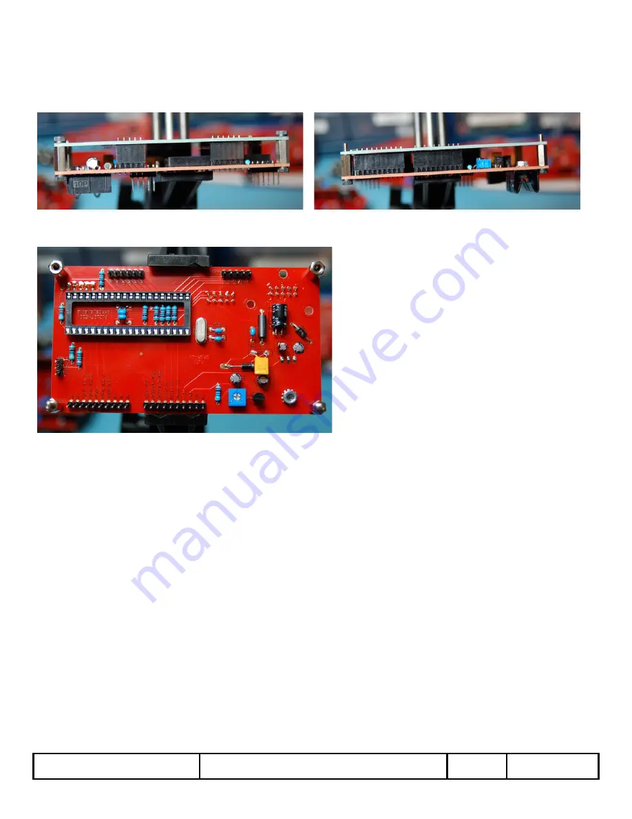
2-17) Next, install the header pairs into their locations so that the male half is installed into the RED Power/Logic PCB. Then, install the
BLUE Signal PCB onto the female half of the header pairs, using the female/male stand-ofs for alignment. Install two more M3 x 6mm
screws into the female/female stand-ofs through the front of the BLUE Signal PCB to secure everything. Double check that each of the
header pairs are in their locations and that everything is aligned well:
2-18) Solder the male headers ONLY to the RED Power/Logic PCB. Do NOT solder the headers to the BLUE Signal PCB:
2-19) Dismantle the RED/BLUE PCB assembly by removing all of the female headers, but leave the stand-ofs in place. You are almost ready
for Power Supply testing, so this is a good time for a break. Stretch out, get a drink, and rest your eyes for a moment. The next steps are
testing and calibrating the power supply circuits, and a sharp mind will help.
When energising your module, there is a chance that an Electrolytic Capacitor can fail, so be sure to
WEAR EYE PROTECTION
to avoid injury
if the base, cap, and contents of the capacitor all decide to spontaneously go their own way!
2-20) Insert Eurorack Power Cable. For testing modules, it is a good idea to use a Bench Power Supply or a regular Eurorack Power Supply
that is dedicated for DIY building with no other modules connected to it – just in case of an electrical mishap. Take one last, close look at
the Chaos Divider Power/Logic PCB for any cold solder joints, pads that are shorted out to nearby pads with blobs of solder [especially on
the Power Supply Header], and the general tidiness of your work. If it looks good, let us continue. Also, if you got ahead of yourself and
inserted the Chaos Engine Microcontroller, be sure to take it out before performing the power supply check.
Connect the Chaos Divider Power/Logic PCB to your power supply of choice and energise. If no “magic smoke comes out” we are ready to
proceed. Set your meter to measure DC Volts and insert the test leads into their appropriate connection ports.
DIY Build DOC/BOM
KOSMODROM CHAOS DIVIDER
V 1.4
Page 12


