
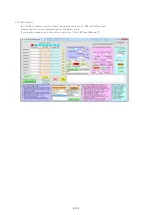
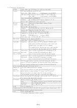

13. Performance and specifications
POWER
AC90~240V 10W (NCT08-01E: +6V 0.85A from NIM BIN)
Counter
TTL Input level Voltage level 3.3V or 5V
(3.3V~5V)
Zin = 10KΩ
Count frequency more 100MHz
NIM Input level Current level -12mA~-36mA:"1" -4mA~+20mA:"0"
Zin = 50Ω
Count frequency more 300MHz
Input Connector
LEMO ERA00250CTL
Channels
0~xxChannels (CH7 is preset counter) xx : 8, 16
digit of count
32bits(0~4,294,967,295)
Encorder
type
Line driver or Open collector ( phaseA,B type)
Counter
input frequency 0~1MHz
power supply
5V for encorder
Channels
2ch (CT08-ER2: ch8, ch9/CT16-ER2:ch15,ch16)
digit of count
32bit(0~4,294,967,295)
termination
120Ω selectable (when Line Driver type)
timer
Number of ch.
1 channel 40bit 1~1,099,511,627,775μs
Resolution
0.000001sec(1μs) Accuracy 0.005%
Preset time
1~ 1,099,511,627,775μs or ms
fixed counter
Number of ch.
1 channel CH7 Fixed
Preset count
1cts ~ 4,294,967 Kcts or cts
Count mode
single mode
By start trigger or "STRT" command, CT08-ER2 counts
input pulse once within preset time or count. Count stops
immediately by stop trigger or "STOP" command.
If you prohibit preset timer stop and count, count operation
never stop unless using stop trigger or "STOP" command.
Count data
synchronous
Store total data automatically up to 10,000 times on the
acquisition mode
gate mode
timing of turning OFF synchronous gate signal.
(save to RAM)
Over 1ms the total time of gate ON and OFF requires.
synchronous
Store total data automatically up to 10,000 times on the
clock mode
timing of turning OFF synchronous clock signal.
Over 1ms the total time of clock RUN and OFF requires.
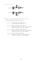
Gate in TTL
TTL Gate input enables count mode control with all channels and timer.
Open or "H" level is count mode. You can invert logic level by inner switches.
Used as a synchronous signal on gate synchronous data acquisition mode.
LED in counting
In count mode LED turn on "green"
Signal out in
TTL output shows counter is now operating.
counting
If you use some modules, you can activate them simultaneously by the
(RUN OUT)
highest module to connect between "TTL output" and "TTL gate in"
on another module. You can invert logic level by inner switches.
If the pulse width is narrower than 10us, it makes the pulse width 10μs.
Control input
Count start input (by TTL rising edge), count stop input (by TTL rising edge)
You can invert logic level by inner switches.
LCD display
number of character 16 columns x 2 lines
value
Count data、timer data、preset count data、timer preset data
count value
0~ 4,294,967,295cts
timer value
0~ 1,099,511.62s
scaling
Can use scaling function
Communication LAN(TCP/IP SOCKET CONNECTION, possible to connect 8connections), USB
Version upgrade upgrade firmware software by communication
Case
EIA2U (H88*W482*D330)
For the further information, feel free to ask us.
42/43


