


1. Specifications
1-1. Abstract
CT08 (16) -ER2 is based on the 8ch counter timer CT08-01D, it is a multifunction machine plus the function
of 2ch encoder counter ER2C-04.Position information and counter information such as when continuously
acquires the count data that depends on the position can be acquired simultaneously.
Set time until 0.000001 seconds to more than 1,000,000 seconds, set number of counts can be set
to any until 1cts ~ 4,294,967Kcts. The case is EIA2. The 16-character × 2-stage LCD display
of larger character size 8 × 5, from among timers and counters and encoder counter,
two channels will be displayed. External communication is a LAN or USB.
In synchronization with the GATE IN signal ON / OFF or internal clock you can collect the data
up to a maximum of 30,000. It can also be used as a counter-timer CT08 (16) -01D.
And it can also be used as an encoder counter ER2C-04.
If you want to collect data in accordance with the timing in timer synchronization and
gate synchronization is a counter-timer function, will be collected at the same time as the counter data
of the data also ch8, ch9 of encoder counter. In the case of the CT16, the data of the encoder counter
will be collected at the same time as the counter data to ch16, ch17.
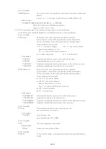
1-2.Appearance(CT08-01E)
Front panel layout
①
②
③
④
⑤
①
Power switch
The lamp of the switch is on when the power is on.
②
LCD display (16 characters and Two lines)
It can display two items from the following 4 items into the two sections (upper row and lower row).
Count value, Timer value, Preset count value, Timer preset value
③
Input connectors for the Counters. There are CH0 to CH17. (INPUT)
It's possible to set preset value only for CH7.
④
It shows the beginning of count action. LED "ON" means the Counter gate open.
⑤
Reset button.
If the pushing is less than 1 second, the same reset action as power-up is executed
If the pushing is more than 3 seconds, the Counter moves to the firmware version up mode.
Please refer to the section "7.Firmware update" for details.
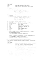
Rear panel layout
⑥
⑦
⑧
⑨
⑩
⑪
⑫
⑬
⑭
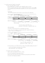
⑥
Connect TTL level signal (3.3 - 5V) from external unit.
START:
When upward edge signal is "ON" ("H"), it starts counting. (INPUT)
Normally (not connected) START signal is "L".
When count mode is selected to "Counter 07 stop" or "Timer stop" and count
value or timer value goes on limit, START can't become true.
User's manual
10/43


