


2-4-4.Stop signal (TTL positive logic)
TTL positive logic signal quits counting action.
The width of stop signal pulse must be more than 100ns.
If pulse width is long, please set to "L" before next start
It's possible to check the count stop status by LED lamp on front panel.
It counts from start signal "ON" to stop signal "ON".
When the stop signal is not used,, it's possible to quit counting by software commands.
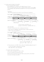
2-4-5.Gate signal (TTL positive logic)
Gate signal is TTL positive logic signal.
When gate signal goes "L" counting action stopped during "L" period. *)
When gate signal goes "L" LED lamp is "OFF" during this period.
LED lamp goes "ON" during gate signal is "H" when counter starts.
When gate signal is no connection, gate signal is equal to logic "H", because of internal pull-up.
When gate signal has been changed to "OFF", the count data are stored in memory on synchronous
gate data acquisition mode.
Memory size is about 5MB. Data can be stored up to 30,000 memory addresses for CT08 type,
and stored up to 15,000 memory addresses for CT16 type.
*) On synchronous gate edge data acquisition mode, the counting action continues to work,
even if gate signal goes "L".
2-4-6.Monitor out signal (In counting, TTL positive logic)
Run signal goes "H" when counting action is valid. It means count start and "Gate signal" are
in "H" logic, and LED goes "ON".
It's useful to use more than two counter units. Connecting this line to "Gate signal input" of another
unit, another units go active counting action.
Please see the section "8. Synchronous drive of multi units" for more details.
You can adjust pulse width, if the signal is difficult to use as trigger for other equipment
because of narrow width (<10μs).
15/43


