


2-3.Setting USB communication
2-3-1.Preparations for setting
Driver software for USB (Universal Serial Bus) operation is downloaded from our web server.
http://www.tsuji-denshi.co.jp/download_file/YS_USBCOM.EXE
By installing this software, connecting is done like a COM port connection.
Switch on a CT48-01E, connect USB cable, then there will be message box that shows "New hardware
device was found (CDC-RS232)". According to PC directions, specify 'the folders of downloaded
driver software.
When the driver software installs are done, open the "Control Panel" ( START → Control Panel),
click the "System" icon. Then property display of system appears. Select the "Device Manager".
Confirm the USB Serial Port (Com*) number in the tree between Port display.
You can see like "YS USB COM Port (COM5)" in port "COM and LPT" in tree.
Select the USB Serial Port (Com*), click Advanced in Port Setting display. It's possible to change
COM Port number. Click the check box Disable PNP □ , it's possible to short operation time in
connecting USB cable again.
You don't need to change RS232C setting like baud rate.
2-3-2. Connecting test
Launch RS-232C communication software such as hyper-terminal including PC.
Set COM port number which is known in previous item, it's need to check communication line is
available or not. In this case It's no need to set baud rate. Send the command data such as "VER?",
then get the reply "1.04 15-05-19 CT08-ER2", there is no problem for communication.
2-4.Connect communication cables
2-4-1.Connect communication cables
Connect the communication cable to USB port or LAN port on rear panel.
There is no need to connect both side, but there will be no problem even if connect both side.
If connected both side, latest command will be valid to the unit.
The Counter accepts 8 LAN connections at the same time.
However, only one connection is available regarding download.
During download, there is no reply message for the speed improvement.
But, the Counter accepts the command to stop download.
During high speed download (hexadecimal download), it may be unable to stop in the middle of run.
Because, the Counter is busy to receive data, and the software may be unable to send the stop
command from the same line. (It becomes easy to occur when COMM monitor is being displayed.)
In this case, you can send the stop command via other software and other LAN/USB port, and stop
the Counter.
2-4-2.Connect count signal
Connect count signal cable to CH0 ~ 15 LEMO connector which are
on front panel. It' s possible to count maximum 16 channel signals.
Before connecting the cable it's need to set signal change switch (TTL side or NIM side), according
to input signal. (See the section 2-1)
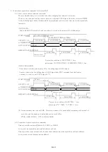
2-4-3. Start signal (TTL positive logic)
TTL positive logic signal starts counting action.
The width of start signal pulse must be more than 100ns.
If pulse width is long, please set to "L" before next stop.
It's possible to check the count start status by LED lamp on front panel.
It counts from start signal "ON" to stop signal "ON".
When the start signal is not used, it's possible to start by software commands.
14/43


