


8.Synchronous drive of multi units
It's possible to operate multi units synchronously.
Then CTXX-01 contains XX CH counters, it's possible to count more channels at synchronous mode
using multi units of the same series.
Here are procedures of this usage.
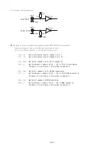
Connect the RUN signal (TTL OUT) of first unit to the GATE signal (TTL IN) port of second unit.
It's the same way to the third unit.
Send "DSAS" command to latter unit. The latter units don't stop counting automatically.
Send "START" command to latter unit. The latter units start counting action.
Depend on your usage, put on "GATE" signal to first unit.
Depend on your usage, preset timer stop command to first unit. ("CLTM","ENTS","STPRdddd")
Depend on your usage, preset counter stop command to first unit. ("CLPC","ENCS","SCPRdddd")
Activate count mode of first unit by the command "START".
This procedure activate more than one unit at the same timing chart.
Similarly, if you use several CTXX-01E,you will acquire multi channels data with gate signal data acquisition.
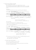
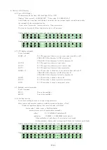
9. Designation and cancellation of RUN output TTL pulse width 10μs at the minimum
A RUN TTL level is outputted when the Counter is busy.
When connecting this signal to other equipment and taking a synchronous, since a pulse width is short,
a reliability may be unable to be kept. For example, since the progress of the Counter is saved in
the memory by internal timer synchronous, OFF time will be set to the minimum time that is 120ns,
if ON time is set to 10ms and OFF time is set to 0μs. However, even if this signal is connected to other
equipments, it may not work well because of the short pulse width. When RUN output is narrower than 10μs,
please execute the command "MIN10U_EN", it makes the minimum pulse width 10μs. MIN10U_DS is the
command to disable "MIN10U_EN".
Please send the command "MIN10U?" to know the status, reply is "EN" or "DS".
10. Regulations and guidelines
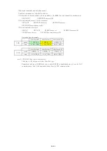
Regarding CT16-ER2 when it receives data read command, it stops count and timer action for 120 ns.
This stopping period is essential to get latest data to latch 32 bits count data.
If you read out count data 20 times/sec, total stopping period of counter is 120ns×20 = 2.4μs/sec.
Even if you read one or all counter at once, all counter and timer stops simultaneously, and
stopping period is always 120ns. Therefore, you may read data by minimum commands.
On timer stop mode or counter stop mode, there is no error measurement caused by counter stop on reading.
For example, a Counter has been set to stop after 1 second by timer stop mode.
If counting value read is done 10 times in 1 second, as compared with the time of not doing a readout,
a timer will stop behind 1.2μs (= 120ns x 10times).
On the other hand, the Counter stopped a total of 1.2 microseconds that is the same period of the Timer.
And the Counter and the Timer has finished the action at the same time.
Therefore, it means that the counting action was done by the specified time.
When in counting pulse during "GATE" signal which comes from outside, you'll notice that counting period
is shorter than read out period.
When in timer stop mode or counter stop mode, there is no dead time to read out count values.
(※) Notes when multiple counter units at simultaneous control
(See 7.Synchronous operation by multi counter units.)
In case of using multiple counter units at simultaneous control, if you read count in progress data of each
units, only units which are read count data stop count operation in 120ns.
Therefore, note that it occurs some errors among count data of modules because of condition of count pulse,
timing of reading, and dispersion of times of reading.
Example: Case of reading 20 times a second to one module only
This module have 120ns * 10 = 1.2μs delay in every seconds.
Count error occurs by 1.2μs/s(0.00012%)
39/43


