background image


3–8 

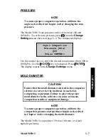
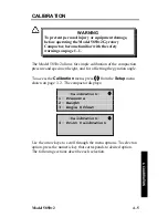
To configure the compactor software for the diameter of the mold in 
use, press 

6


from the 

Change Settings

 menu on page 3–4. The 

compactor displays: 
 

-Mold Diameter- 

1- 150mm 
2- 100mm 
3- 4in 

 
Press the numeric key that corresponds to the desired mold 
diameter. The compactor displays a brief confirmation message, and 
then returns to the Mold Diameter menu shown above. Press 

ESC


to return to the 

Change Settings

 menu shown on page 3–4. 


POST GYRATE DELAY 

The Model 5850v2 provides the option for a five-minute delay upon 
completing the compaction of a specimen. This delay maintains a 
minimum pressure on the sample and allows low gyration 
specimens to cool before the ram lowers.  
 
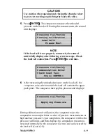
Press 

SETUP

 button, and 

Change Settings

 
To enable the Post Gyration Delay, scroll using the ↑↓ buttons, press 

7

 from the 

Change Settings

 menu. The compactor displays:  


-Post Gyrate Delay- 

1- Enable 
2- Disable 
3- Set Delay Time 

 
Press 

1

 to enable the function and press 

2

 to disable it. The 

compactor briefly displays the message 

Post Gyration Delay is 

Enabled

 (or 

Disabled

). 

Summary of Contents for 5850v2

Page 1: ...ly important to understand the Safety Warnings on page 1 1 Keep this manual in a safe place that is always easily accessible during the use of the Model 5850v2 Troxler Electronic Laboratories Inc 3008...

Page 2: ...ans electronic or mechanical including photocopying recording or information storage and retrieval systems for any purpose without the express written permission of Troxler Electronic Laboratories Inc...

Page 3: ...1430 Brook Drive Downers Grove IL 60515 Phone 1 630 261 9304 Fax 1 630 261 9341 TroxTechSupport troxlerlabs com WESTERN BRANCH OFFICE SERVICE CENTER 11300 Sanders Drive Suite 7 Rancho Cordova CA 9574...

Page 4: ...es the compactor keypad and provides instructions for setting up starting and operating the compactor Chapter 3 Setup Menu Provides a detailed description of the options available from the compactor s...

Page 5: ...troubleshooting and general maintenance Do not attempt to operate the Model 5850v2 before reading this manual and the safety warnings posted on the unit Troxler stresses that the user is solely respo...

Page 6: ...o ensure proper operation KEY Angle brackets and a different typestyle indicate a key or character number or letter to press on the compactor keypad For example Press START means to press the key labe...

Page 7: ...cting a Specimen 2 6 Cleaning and Lubricating 2 8 Preparing a Specimen 2 10 Compacting the Specimen 2 14 Removing the Sample from the Mold 2 15 Cooling the Sample 2 16 Shear Options Performance Tests...

Page 8: ...4 Replacing the Batteries A 7 Cleaning the Cooling Fan A 8 Replacement Parts A 8 Returning Parts for Service A 9 APPENDIX B B 1 Menu Map Description B 2 APPENDIX C C 1 Environmental Conditions C 2 Ele...

Page 9: ...ill Tube 1 13 Figure 2 1 Model 5850v2 Control Panel Layout 2 3 Figure 2 2 Compaction Chamber 2 9 Figure 2 3 Loading the Mold 2 12 Figure 3 1 Sample Height Versus Gyration Table 3 13 Figure 4 1 Alignin...

Page 10: ...x LIST OF TABLES Table Title Page Table 2 1 Control Panel Keys and Button 2 2...

Page 11: ...le of improper or unauthorized use of this unit that may lead to malfunction or accident Thus if a particular use is not specifically mentioned in this manual as authorized then consult Troxler about...

Page 12: ...y when operating the compactor Keep hands away from the gyratory compactor when the unit is in motion With the service panels removed the gyratory compactor poses an electrical hazard Unplug the gyrat...

Page 13: ...ts Lower Left Side of Compactor Connection for 100 240 VAC 50 60 Hz power to the compactor Upper Left Side of Compactor 9 pin RS 232C serial interface for connecting the compactor to a computer or ser...

Page 14: ...obtaining meaningful test results Building upon the successes of Troxler s Model 4140 and 4141 Gyratory Compactors the Model 5850v2 has been completely redesigned with improved electronics a robust c...

Page 15: ...e reading this manual and the safety warnings posted on the unit Troxler stresses that the operator is solely responsible for ensuring the safe use of the Model 5850v2 The manufacturer its subsidiarie...

Page 16: ...ciety of Testing and Materials ASTM SI10 Standard for Use of the International System of Units SI The Modern Metric System CARE AND MAINTENANCE The Model 5850v2 requires little maintenance To reduce t...

Page 17: ...Model 5850v2 1 7 1 INTRODUCTION Figure 1 1 Model 5850v2 Gyratory Compactor...

Page 18: ...s the compactor to the printer or other USB device Part number 110697 The serial cable not shown connects the compactor to a serial device such as a computer Part number 106514 The extruder is used to...

Page 19: ...see that the following are included Model 5850v2 Gyratory Compactor Mold Power cord Height standard assembly Specimen papers 500 per package Printer USB cable Serial cable Manual of Operation and Ins...

Page 20: ...nit cut each side of the carton approximately 2 inches above the pallet Lift the carton up and off the unit 2 2 Remove the metal strap and bolts that secure the compactor to the pallet 3 3 Remove the...

Page 21: ...ite Place the compactor on a flat level location Locate the compactor no more than 1 2 m 4 ft from the required electrical power source see Appendix C Ensure that the distance does not place stress on...

Page 22: ...ISO VG 32 SAE 10 Troxler part number 018203 hydraulic oil to fill the hydraulic reservoir 2 2 Ensure that the oil level is at the 30 degree mark on the sight glass as shown in Figure 1 3 If oil is ne...

Page 23: ...Model 5850v2 1 13 1 INTRODUCTION Figure 1 3 Proper Reservoir Fill Level Figure 1 4 Place a Funnel in Reservoir Fill Tube ENSURE FLUID LEVEL IS AT 30 DEGREE MARK FUNNEL...

Page 24: ...code requirements Refer to the Electrical Specifications section on page C 3 for the current and voltage ratings for the compactor 7 7 If using the compactor with a USB printer or memory device conne...

Page 25: ...OPERATION This chapter describes how to get started using the Model 5850v2 Gyratory Compactor This information includes a brief description of the control panel and instructions for turning the compac...

Page 26: ...setting or viewing the run options setting the data output options calibrating the compactor verifying the calibration and clearing project data ESC Returns to the next higher level menu without upda...

Page 27: ...Model 5850v2 2 3 2 SETUP OPERATION Figure 2 1 Model 5850v2 Control Panel Layout...

Page 28: ...number of gyrations this value is 999 if the compactor is set to compact to a target specimen height AI Operator selected internal angle of gyration P Operator selected compaction pressure FIRST TIME...

Page 29: ...gs selection The compactor displays Selected run count number of gyrations Selected mode number of gyrations or specimen height Specimen height Gyration angle Ram pressure Mold diameter Gyrate Delay R...

Page 30: ...ibed on page 3 11 NOTE Before outputting data to a printer or computer ensure that the Model 5850v2 is properly connected to the output device COMPACTING A SPECIMEN WARNING To prevent personal injury...

Page 31: ...e mold 5 5 Place the mold in the compactor chamber and compact the specimen 6 6 Remove the mold containing the compacted specimen from the compactor chamber and extrude the asphalt specimen using the...

Page 32: ...head and the upper puck plate with Magnalube G 4 4 Clean the mold and pucks with Bindoff or similar cleaner CAUTION Do not use a degreasing cleaner or glass cleaner to clean the clear chamber door To...

Page 33: ...Model 5850v2 2 9 2 SETUP OPERATION LOWER CARRIAGE PLATE RAM HEAD MOLD TRAY VIEW A UPPER PUCK PLATE UPPER CARRIAGE ASSEMBLY VIEW B Figure 2 2 Compaction Chamber...

Page 34: ...CAUTION Do not heat the mold above 175 C 350 F Heating above this temperature may warp the mold and create errors in the angle of gyration NOTE Do not place the asphalt mixture into the mold while hea...

Page 35: ...Model 5850v2 2 11 2 SETUP OPERATION part numbers 106952 or 106953...

Page 36: ...while inserting it to prevent it from becoming wedged in the mold CAUTION If the upper or lower puck becomes wedged in the mold it must be removed and inserted correctly before compacting the asphalt...

Page 37: ...Model 5850v2 2 13 2 SETUP OPERATION the chamber door...

Page 38: ...amber door Press START If there is no mold in the chamber or if the mold is not in the proper location the compactor displays an error message If the mold is in place the compactor begins the compacti...

Page 39: ...ght data The compactor then returns to the Machine Idle display shown on page 2 4 Open the chamber door and wearing heat resistant gloves remove the mold from the compaction chamber Extrude the specim...

Page 40: ...that measure the shear forces acting on the specimen during gyration The Model 5850v2 also utilizes the Gyratory Shear Kit GSK which turns any gyratory compactor into a shear enabled unit without the...

Page 41: ...1 3 SETUP MENU CHAPTER 3 SETUP MENU The compactor s Setup menu enables the operator to select and define the operating parameters of the Model 5850v2 Gyratory Compactor This chapter describes the man...

Page 42: ...compaction data to calibrate the compactor and to perform other special functions To access the Setup menu press SETUP on the keypad Use the arrow keys to scroll through the menu options To select an...

Page 43: ...s select View Settings from the Setup menu shown on page 3 2 The compactor displays Selected run count number of gyrations Selected mode number of gyrations or specimen height Specimen height Gyration...

Page 44: ...yration angle 0 00 to 3 0 degrees Define the desired ram pressure 200 to 1000 kPa Select the mold diameter 150 mm 100 mm or 4 inch To access these options press 2 from the Setup menu see page 3 2 The...

Page 45: ...ration Mode menu shown below Operation Mode 1 Gyrations 2 Specimen Height Press to Select Press the numeric key that corresponds to the desired operation mode The compactor displays a brief confirmati...

Page 46: ...isplays Input Target Specimen Height mm 115 0 Press ENTER Use the number keys to enter the specimen height 50 to 200 mm Use the NO CE key to backspace Press ENTER The display returns to the Change Set...

Page 47: ...pressure from 200 to 1000 kPa Use the NO CE key to backspace Press ENTER The display returns to the Change Settings menu MOLD DIAMETER CAUTION Ensure that the mold diameter selected in the compactor...

Page 48: ...n on page 3 4 POST GYRATE DELAY The Model 5850v2 provides the option for a five minute delay upon completing the compaction of a specimen This delay maintains a minimum pressure on the sample and allo...

Page 49: ...en the post gyrate delay is enabled after gyrations are complete the screen will display NOTE Where MM represents minutes and SS represents seconds During the delay the pump remains on The carriage pl...

Page 50: ...roduct page on the Troxler website www troxlerlabs com The output data can be presented in either a height versus gyration or full table format These options are described on page 3 12 NOTE Before out...

Page 51: ...he Data Output menu shown on page 3 10 The compactor searches the data records and then displays the specimens currently stored in memory as shown below 04 08 09 04 24P 04 08 09 01 52P 04 08 09 08 45A...

Page 52: ...ta Output menu The GyroImport software is used to convert the data on the USB memory device to a Microsoft Excel workbook The software may be downloaded from the 5850v2 product page on the Troxler web...

Page 53: ...nd then returns to the Data Output menu Press 3 to select GyroPave software compatible data format The data is similar to the Table format but only height measurements are output The compactor display...

Page 54: ...n press 4 from the Setup menu see page 3 2 The compactor drives the four actuators to their home position while displaying Moving Gyratory to Home Position When the actuators are in their home positio...

Page 55: ...llows for simple calibration of the specimen height and compaction pressure and for offsetting the angle of gyration This chapter provides a recommended schedule for calibration and verification of th...

Page 56: ...er changing the ram pressure see page 3 7 PRESSURE CALIBRATION See page 4 6 for details on pressure calibration Calibrate the compaction pressure every 3 months SPECIMEN HEIGHT CALIBRATION See page 4...

Page 57: ...able from Troxler part number 108706 To verify the internal angle follow the instructions in Chapter 3 to 1 1 Set the operation mode to number of gyrations 2 2 Set the number of gyrations to 20 3 3 Se...

Page 58: ...ition 2 8 8 Follow the instructions provided with the internal angle device to measure the top angle Ensure that the probes of the internal angle device are aligned along Position 1 with the edge of t...

Page 59: ...tion of the compaction pressure and specimen height and for offsetting the gyration angle To access the Calibration menu press 5 from the Setup menu shown on page 3 2 The compactor displays Calibratio...

Page 60: ...or asphalt clean the mold tray ram head lower carriage plate upper carriage assembly and upper puck plate see Figure 2 2 on page 2 9 with Bindoff or similar cleaner 2 2 Connect the load cell as follo...

Page 61: ...bration load cell in the center of the puck as shown below 3 3 Place the upper puck larger edge down centered on top of the load cell 4 4 Route the load cell cables through the notch in the upper cent...

Page 62: ...4 8 Figure 4 3 Routing Load Cell Cables ROUTE CABLES THROUGH NOTCH LOAD CELL...

Page 63: ...nection Press ENTER to continue Pressure Cal Verify Communication Error Check Load Cell Press ENTER 6 6 After measuring the unloaded pressure on the load cell the compactor raises the ram until the lo...

Page 64: ...9 Open the chamber door and remove the calibration load cell and pucks Unplug the dc charger from the electrical outlet and disconnect the load cell from the dc charger and control unit Return all pa...

Page 65: ...3 3 Close the chamber door and press ENTER The compactor displays Height Calibration Enter Std Height Press ENTER The height of the height standard assembly is stamped on its side Enter the height to...

Page 66: ...commends verifying the angle after every 800 samples or once per year using an internal angle device such as the Dynamic Angle Verification DAV device available from Troxler Refer to page 4 3 for inst...

Page 67: ...e is the value just entered Angle Offset Degrees 1 Change 2 Enable To enable the Angle Offset function using this value press 2 PRINT CALIBRATION The Print Calibration function can be used to manually...

Page 68: ...4 14 NOTES...

Page 69: ...APTER 5 SPECIAL FUNCTIONS The Model 5850v2 Gyratory Compactor firmware includes a number of functions that typically are not used on a day to day basis These functions are accessed from the Special me...

Page 70: ...ll project specimen data and to reset the software To access these functions press 6 from the Setup menu The compactor displays the Special menu shown below Special 1 Clock Calendar 2 Erase Records 3...

Page 71: ...shown below Use the arrow keys to scroll through the menu options To select an option press the numeric key that corresponds to desired option The following sections describe each selection Clock Cale...

Page 72: ...ar menu shown on page 5 3 The compactor displays 04 08 2009 mm dd yyyy Input Date and Press ENTER Note that in this example the date is displayed in mm dd yyyy format To change the format see the Date...

Page 73: ...that corresponds to the desired time format The compactor returns to the Clock Calendar menu DATE FORMAT The compactor can display the date in either mm dd yyyy or dd mm yyyy format where mm month dd...

Page 74: ...the Special menu shown on page 5 2 The compactor displays Permanently Erase all Data Records YES or NO To erase all data records press YES The compactor restores the default settings displays a brief...

Page 75: ...tants stored in the compactor memory To use this function press 3 from the Special menu shown on page 5 2 The compactor displays System Reset Sets System Variables to Defaults Continue YES or NO To re...

Page 76: ...5 8 NOTES...

Page 77: ...Model 5850v2 Appendix A 1 A TROUBLESHOOTING APPENDIX A TROUBLESHOOTING AND SERVICE This appendix contains information on servicing and maintaining the Model 5850v2 Gyratory Compactor...

Page 78: ...the circuit breaker is not tripped Moving parts are not moving 1 1 Ensure the unit is turned on 2 2 Check that the chamber door is closed 3 3 A switch may be broken Check the service panels and emerg...

Page 79: ...erlabs com General calibration problems 1 1 Check all cable connections 2 2 For the height calibration ensure that the puck specimen papers and height standard assembly are located properly on the low...

Page 80: ...wer carriage plate including the mold positioning pins and ram head see Figure 2 2 View A on page 2 9 as well as the upper carriage assembly and upper puck plate View B with Bindoff or similar cleaner...

Page 81: ...eplacement is necessary contact your Troxler representative Mold positioning pins in the lower carriage plate Check for wear or flattening Replace if necessary Pucks Ensure that the surfaces are reaso...

Page 82: ...ce the hose and sleeve 6 6 Open the chamber door and examine each hydraulic hose for wear If the rubber cover is worn replace the hose EVERY 500 HOURS OF OPERATION OR ONCE A YEAR 1 1 Remove the right...

Page 83: ...e connector see Figure 1 1 on page 1 7 2 2 Remove the four screws that secure the control panel 3 3 Carefully remove the control panel using care not to damage any of the cables connected to it 4 4 Th...

Page 84: ...cations 110665 Gravity extruder 106989 Height standard assembly 116066 Mold assembly 100 mm 116069 Mold assembly 150 mm 116901 Model 5850v2 Manual of Operation and Instruction 108664 Power cord 13 A 1...

Page 85: ...part model and serial number Part number serial number if applicable Is the unit part still under warranty Problem or difficulty you are having with the unit Shipment method to Troxler and for return...

Page 86: ...Appendix A 10 NOTES...

Page 87: ...Model 5850v2 Appendix B 1 B MENU MAP APPENDIX B MENU MAP This appendix provides a map of the menus in the Model 5850v2 Gyratory Compactor control software...

Page 88: ...ion Mode 1 Gyrations 2 Specimen Height This indicates that the first two menu items under the Setup menu are View Settings and Change Settings When the Change Settings item is selected the compactor d...

Page 89: ...cimen Height 2 of Gyrations 3 Height 4 Angle 5 Pressure 6 Mold Diameter Mold Diameter 1 150mm 2 100mm 3 4in 7 Post Gyrate Delay Post Gyrate Delay 1 Enable 2 Disable 3 Data Output Data Output 1 Output...

Page 90: ...Calibration 1 Pressure 2 Height 3 Angle Offset 4 Print Calibration 6 Special Special 1 Clock Calendar Clock Calendar 1 Change Time 2 Change Date 3 Time Format Time Format 1 AM PM 2 24 Hour 4 Date For...

Page 91: ...TIONS APPENDIX C SPECIFICATIONS This appendix provides environmental conditions and specifications for the Model 5850v2 Gyratory Compactor CONTENTS Environmental Conditions C 2 Electrical Specificatio...

Page 92: ...ge 55 to 85 C Temperature 67 to 185 F Ambient Operating 10 to 50 C Temperature 50 to 122 F Altitude Rating 2000 meters maximum Main Supply Voltage 10 Fluctuation Pollution Degree 2 Installation Catego...

Page 93: ...arity Baud rate 9600 Cable type RS 232 null modem 9 pin female 9 25 pin female USB Port A list of compatible USB memory devices and printers is available on the 5850v2 product page at www troxlerlabs...

Page 94: ...Puck Weight 3 kg 6 6 lb Compaction Pressure 200 1000 kPa 29 145 psi Pressure Accuracy Meets or exceeds FHWA specifications Number of Gyrations Adjustable from 1 999 Angle of Gyration 0 00 3 0 0 02 de...

Page 95: ...15 Batteries replacing A 7 Baud rate C 3 Bindoff ii 2 8 4 6 4 8 Cable Serial 1 8 USB 1 8 Calibration 4 1 Calibration constants 4 10 4 12 5 7 Menu 4 5 Pressure 4 2 4 6 Print 4 13 Problems A 3 Schedule...

Page 96: ...3 12 GyroPave 3 13 Height standard assembly 1 8 4 11 Height versus gyration format 3 10 Height specimen 3 6 Home position 3 14 Humidity C 2 Hydraulic oil 1 12 C 4 A 5 A 2 Inspection 1 9 Installation c...

Page 97: ...1 14 C 3 USB 1 3 1 14 C 3 Power Requirements C 3 Switch 1 8 2 4 Pressure 3 7 Accuracy C 4 Calibration 4 2 4 6 Compaction 1 5 C 4 Verification kit 1 8 4 6 Print Calibration 4 13 Printer 1 8 Puck 1 8 Ra...

Page 98: ...6 Height calibration 4 2 4 10 Loading 2 13 Papers 1 8 2 11 Preparing 2 11 START key 2 2 Storage temperature C 2 Supply voltage fluctuation C 2 Switch EMERGENCY 1 4 2 2 Switch power 1 8 2 4 Target heig...

Page 99: ...Model 5850v2 Index...

Page 100: ...NOTES...

Page 101: ...ractual or other written and signed agreement THERE ARE NO WARRANTIES WHICH EXTEND BEYOND THE DESCRIPTION ON THE FACE HEREOF AND THIS WARRANTY IS EXPRESSLY IN LIEU OF ALL OTHER WARRANTIES EXPRESSED OR...

Page 102: ...12...

Reviews: