Appendix B–2
MENU MAP DESCRIPTION
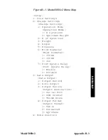
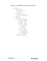
Figure B–1 is a map of the compactor’s
Setup
menu and each of its
submenus. To access the
Setup
menu, press
Setup
. Where
applicable, the default (as shipped) menu settings are shown in
shaded text.
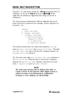
The menu map uses indentation to indicate submenus that result
from selection of a menu item. For example, the first eight lines of
Figure B–1 are:
-Setup-
1– View Settings
2- Change Settings
-Change Settings-
1- Operation Mode
-Operation Mode-
1- # Gyrations
2- Specimen Height
This indicates that the first two menu items under the
–Setup-
menu are
View Settings
and
Change Settings
. When the
Change Settings
item is selected, the compactor displays the
Change Settings
submenu.
The first menu item under
the Change Settings
submenu is
Operation Mode
. When this item is selected, the compactor
displays the
Operation Mode
submenu, which has two menu
items,
# Gyrations
and
Specimen Height
.
NOTE
The menu map contains only the displays that allow or
require a choice by the operator. Other displays (such as
numerical entries, status information, confirmation
messages, or error displays) are not included.
Summary of Contents for 5850v2
Page 10: ...x LIST OF TABLES Table Title Page Table 2 1 Control Panel Keys and Button 2 2...
Page 17: ...Model 5850v2 1 7 1 INTRODUCTION Figure 1 1 Model 5850v2 Gyratory Compactor...
Page 27: ...Model 5850v2 2 3 2 SETUP OPERATION Figure 2 1 Model 5850v2 Control Panel Layout...
Page 35: ...Model 5850v2 2 11 2 SETUP OPERATION part numbers 106952 or 106953...
Page 37: ...Model 5850v2 2 13 2 SETUP OPERATION the chamber door...
Page 62: ...4 8 Figure 4 3 Routing Load Cell Cables ROUTE CABLES THROUGH NOTCH LOAD CELL...
Page 68: ...4 14 NOTES...
Page 76: ...5 8 NOTES...
Page 86: ...Appendix A 10 NOTES...
Page 99: ...Model 5850v2 Index...
Page 100: ...NOTES...
Page 102: ...12...

