2HJ/2HK
1-5-42
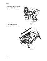
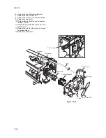
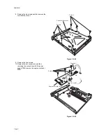
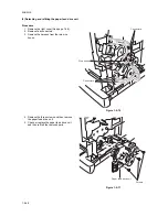
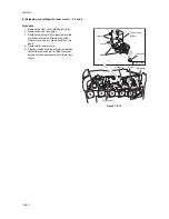
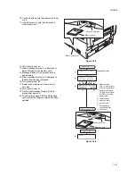
8. Remove the six screws and then remove the
controller box cover.
Figure 1-5-62
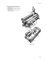
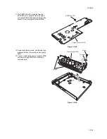
9. Remove the five screws.
10. Remove the two connectors and then
removing the connection with the power
supply PWB, remove the engine controller
PWB.
Figure 1-5-63
Screws
Screws
Controller box cover
Engine controller PWB
Connector
Connector
Screws
Summary of Contents for CLP3316
Page 1: ...Service Manual Color Printer CLP 3316 CLP 3520 X First Edition Date 24 10 2006 2HKSM060 ...
Page 2: ...Service Manual Color Printer CLP 4316 CLP 4520 X First Edition Date 24 10 2006 2HKSM060 ...
Page 6: ...This page is intentionally left blank ...
Page 12: ...This page is intentionally left blank ...
Page 20: ...2HJ 2HK 1 1 8 This page is intentionally left blank ...
Page 32: ...2HJ 2HK 1 2 12 This page is intentionally left blank ...
Page 138: ...2HJ 2HK 1 6 4 This page is intentionally left blank ...
Page 168: ...2HJ 2HK 2 1 30 This page is intentionally left blank ...
Page 172: ...2HJ 2HK 2 2 4 This page is intentionally left blank ...
Page 188: ...2HJ 2HK 2 4 6 This page is intentionally left blank ...

