background image

SeaKing Sidecan Sonars

0374-SOM-00013, Issue: 01

44

© Tritech International Ltd.

15. Software Functions

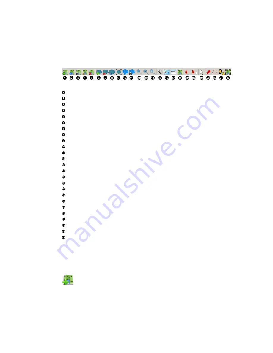
15.1. Toolbar

Import chart

Export as image

Save project

Load project

Clear project

Add tile

Delete all tiles

Reset all tiles

Resize tile

Create mosaic

Save mosaic

Zoom in

Fit to screen

Zoom out

Toggle coordinates dialog

Toggle coordinate system dialog

Toggle tile list dialog

Toggle chart

Show markers

Move marker

Pan tool

Erase tool

Area erase tool

Remove tile background

Export area

15.1.1. Project Controls

Import/Create Chart

For  creating  a  blank  chart  or  importing  a  previously  created  chart.  For  more

information on this function please see Section 16.2, “Create the Background Chart”.

Summary of Contents for ROV Sidescan

Page 1: ...SeaKing Sidecan Sonars Towfish SK150 and ROV Sidescan 0374 SOM 00013 Issue 01 ...

Page 2: ... document is supplied by Tritech International Ltd on the understanding that it may not be copied used or disclosed to others except as authorised in writing by Tritech International Ltd Tritech International Ltd reserves the right to change modify and update designs and specifications as part of their ongoing product development programme All product names are trademarks of their respective compa...

Page 3: ...operties 13 4 3 Electrical Communication Software 13 4 4 Acoustic Properties 14 II Installation 15 5 Installing the ROV Sidescan 16 5 1 Transducer Orientation 16 5 2 Communications 17 5 3 Power 17 6 Installing the Towfish 19 6 1 Cable and Strain Relief 19 6 2 Communications 19 6 3 Power 20 7 Installing the SK150 21 7 1 Cable and Strain Relief 21 7 2 Communications 21 7 3 Power 22 III Seanet Pro So...

Page 4: ... Create the Background Chart 57 16 2 1 Image with World File 58 16 2 2 Image with Manual Positional Data 59 16 2 3 Blank Chart 60 16 2 4 Co ordinate System 60 16 3 Add Image Tiles 61 16 4 Manipulate Image Tiles 61 16 5 Save the Project 61 16 6 Exporting the completed mosaic as an image 62 17 Supported File Formats 64 17 1 For Loading Tiles 64 17 2 Saving Images or Mosaics 64 17 3 Project Files 65 ...

Page 5: ...r firmware revision numbers 3 A clear fault description 4 Details of any remedial action implemented Contamination If the product has been used in a contaminated or hazardous environment you must de contaminate the product and report any hazards prior to returning the unit for repair Under no circumstances should a product be returned that is contaminated with radioactive material The name of the ...

Page 6: ...urrent topic Important When this is shown there is potential to cause harm to the device due to static discharge The components should not be handled without appropriate protection to prevent such a discharge occurring Caution This highlights areas where extra care is needed to ensure that certain delicate components are not damaged Warning DANGER OF INJURY TO SELF OR OTHERS Where this symbol is p...

Page 7: ...ctronics pod The SK150 is a specially designed Towfish that can withstand higher pressures found in deeper water Communication between the surface computer and the devices can be via RS232 RS485 or ARCNET protocols The ROV mounted device can be combined with the Tritech International Ltd Subsea Junction Box which will allow other devices such as the SeaKing or Hammerhead Sonar to be used on the sa...

Page 8: ...SeaKing Sidecan Sonars 0374 SOM 00013 Issue 01 8 Tritech International Ltd Part I Specification ...

Page 9: ...s in mm 2 2 Dimensions of Transducers Not to scale dimensions in mm SIDE VIEW TOP VIEW side mounting holes suit M6x1 screw 6 3mm through 34 75 75 32 top mounting holes x4 to suit M6x1 6 3mm through counterbored 10mm to 7mm 10 24 46 500 2 3 Physical Properties Property Electronics Pod Transducers Weight in air 2 5kg 1 4kg each Weight in water 1 6kg 0 54kg each Depth rating 4000m Connector Tritech 6...

Page 10: ...ata log format Tritech V4Log as standard Export to XTF TIFF GeoTIFF and Google Earth KMZ via converter 2 5 Acoustic Properties Frequency 325kHz 675kHz Beamwidth 30 vertical 1 horizontal 30 vertical 0 5 horizontal Maximum range 200m 100m Pulse length 400μs 200μs Source level 200dB re 1μPa at 1m Sensitivity Better than 2μV rms Gain control 80dB Dynamic range 40dB configurable Sample rate 5 200μs Dat...

Page 11: ...nose cone Operating temperature 10 C to 35 C Storage temperature 20 C to 50 C 3 3 Electrical Communication Software Power 24V DC at 12VA Communication ARCNET RS485 RS232 optional Cable Standard 6 7mm diameter Kevlar re inforced cable Supplied in lengths of 100 and 150 metres Software Tritech Seanet Pro ChesaPeake SonarWiz real time interface Low level direct access and control Data log format Trit...

Page 12: ...orizontal 30 vertical 1 horizontal Pulse length 400μs 30 vertical 1 horizontal Range 200m 100m Source level 200dB re 1μPa at 1m Gain control range 80dB Display dynamic range 40dB configurable Data resolution 4 8 bits configurable Receiver sensitivity Better than 2μV rms Note The SeaKing Towfish is supplied as either a High Frequency or Low Frequency sonar and is not switchable ...

Page 13: ...Materials Polyester powder coated aluminium Operating temperature 10 to 35 C Storage temperature 20 to 50 C Maximum towing speed 5 knots 4 3 Electrical Communication Software Power requirement 36 48V DC 300mA at 36V Connector Tritech standard 6 pin waterblock Cable Wire armoured Software Tritech Seanet Pro or low level direct access and control Data log format Tritech V4Log as standard Export to X...

Page 14: ...13 Issue 01 14 Tritech International Ltd 4 4 Acoustic Properties Operating frequency 150kHz Beamwidth 60 vertical 1 4 horizontal Maximum range 350m Minimum range 0 4m Range resolution 5 300mm Source level 210dB re 1μPa at 1m Pulse length 400μs Bandwidth 40kHz ...

Page 15: ...SeaKing Sidecan Sonars 0374 SOM 00013 Issue 01 15 Tritech International Ltd Part II Installation ...

Page 16: ...e To increase the maximum range the angle can be reduced to 10 and the ROV height above the seabed increased but doing so will increase the size of the blind area underneath the ROV Targets may be missed if the ROV is flown directly over the top of them A guard can be fitted to the ROV to protect from impact damage but this must not overlap the transducer area or it may have an effect on the sonar...

Page 17: ...xiliary devices such as altimeters oceanographic sensors and scanning sonars The AUX port may be blanked off The MAIN connector and optional AUX connector are wired as follows Tritech Waterblock Pin Function Cable colour 1 ARCNET A RS232 TX Yellow 2 ARCNET B RS232 RX Blue 3 DC Red 4 DC Black 5 RS232 Ground Green 6 Earth cable shield cable screen Note If communicating using the ARCNET protocol it w...

Page 18: ... for a single device If other SeaKing devices are connected via the AUX port in a network then the loop resistance should be 5Ω for two devices and 3Ω for three devices If the supply voltage is less than the minimum specified in Chapter 2 SeaKing ROV Sidescan the Sidescan is unlikely to work correctly Ground Fault Monitoring Equipment The power supply within all SeaKing devices includes an electri...

Page 19: ...train relief in place The tow arm is connected to the tow bar on the body using a pivot assembly and pivot pin which is designed to shear if the Towfish is subject to impact whilst under way This will enable the Towfish to be recovered tail first and should prevent it from becoming entangled An acetal tail cone is screwed on the rear end which can be unscrewed to enable the removal of the safety w...

Page 20: ...over a longer cable by increasing the voltage above the maximum specified doing so may cause permanent damage If using a rectified transformer PSU the output must have a filter capacitor of at least 470μF for each head that is being powered The use of unregulated power supplies is not recommended If powering the head down a long lead or umbilical the maximum recommended loop resistance of the powe...

Page 21: ...lling pressure Also the bow pin on the tow cable mounting shackle will shear when excessive pulling pressure is applied If the fins hit a hard object they will break off and can be easily replaced on recovery of the SK150 7 2 Communications The SeaKing Towfish is fitted with a standard Tritech waterblock connector This is a 6 pin connector and is wired as follows Tritech Waterblock Pin Function Ca...

Page 22: ...f at least 470μF for each head that is being powered The use of unregulated power supplies is not recommended If powering the head down a long lead or umbilical the maximum recommended loop resistance of the power line must not exceed 10Ω If the supply voltage is less than the minimum specified in Chapter 4 SeaKing Towfish SK150 the SK150 is unlikely to work correctly Ground Fault Monitoring Equip...

Page 23: ...SeaKing Sidecan Sonars 0374 SOM 00013 Issue 01 23 Tritech International Ltd Part III Seanet Pro Software Suite ...

Page 24: ...be displayed on one screen It is also possible to log the sonar data and store it on the computer hard drive Seanet Setup This is included as part of Seanet Pro and it is not possible to install it separately Using this program it is possible to re configure the sonar by changing communication protocols or baud rates It is also possible to choose which serial port the sonar is connected to if ther...

Page 25: ...n the installation program starts click Next to continue Read the license agreement and if you agree to its terms select the YES option and click Next to continue Confirm the installation destination directory by default C Program Files SeanetV2 but if you wish to change this click the browse button and select an alternative directory click Next to continue Installation will then copy files onto y...

Page 26: ...cation Tools The Sidescan echo return data may be displayed with time marks and text labelling and the software has the option to output the data to a thermal plotter via a parallel port interface To set up Seanet Pro for use with a SeaKing Sidescan first launch Seanet Pro and then navigate to the Applications menu and select Application Wizard In the configuration wizard which presents itself sel...

Page 27: ...isplay window for each device that is connected to the system It includes a Tools Setup button status indicator pause go and RAT dials and buttons 4 Status Bar this part of the screen is used to display system status information logging status progress and job specific information 5 Sensor Display Area this part of the screen is where the main Sidescan data is displayed Other pertinent data such a...

Page 28: ...sonar will scan Long ranges are scanned more slowly than short ranges due to the limit imposed by the velocity of sound in water and may require a slower vehicle speed if the the Sidescan is being towed Resolution F4 Resolution toggles through 4 preset sampling periods over the pulsed range Lo resolution produces the least samples and gives the lowest resolution The number of samples is increased ...

Page 29: ...plays the Range and Time Move the mouse pointer over the Sidescan waterfall display to update the cursor position giving Range to pointer and Time of scan line that the pointer is positioned over Note If the system has real time GPS position and heading data input the panel will extend to additionally display the target coordinates Display Controls all the display options ...

Page 30: ... off Text Toggle event text on off Event Interval Set a time interval of 1 60s between events This is not applicable to Manual Text events Event Text Text1 is displayed on the left and Text2 is displayed on the right Choose from None no event text displayed PC DateTime current date and time from the control computer Manual Text enter text via the text box and click the Annotate button Remote Text ...

Page 31: ... data if un checked the intensity will be set at 4 bit Detects Paint the leading edge of strong targets on the screen used to emphasise sub bottom layers Scrn Lock Locks the number of range bins sampled to the screen resolution This over rides the Resolution F4 control Lockout Sets a minimum lockout range for the detects always in metres Units Waterfall display range units metres feet fathoms or y...

Page 32: ...he left right or both channels to be chosen as the output Line Repeat stretches the printout by repeating line printouts 0 off Sidescan This is where the Sidescan channel settings are configured Interleaved Scan This button becomes enabled when a DST Sidescan is connected The DST Sidescan has capability to fire both channels at the same time as opposed to in ping pong mode and this control enables...

Page 33: ... need to be adjusted from its default position as shown on the left However if used properly adjusting the sample window can produce better quality imaging The dynamic range bar can be adjusted to change Sonar display contrast and sensitivity Adjustment is made using the left and right mouse buttons Contrast adjustment Right click on the bar and whilst holding down the right button move the mouse ...

Page 34: ...d low level returns seen at the receiver The sonar receiver will accept a return signal in the region of 0 80dB The dynamic range controls are used to adjust the position of a sampling window within the 0 80dB dynamic range band of the receive signal An idealised representation of the sample window is shown ...

Page 35: ...ire a log file from Seanet Pro 2 Launch Seanet Dumplog and load the previously recorded log file 3 Select the sonar type that has been used in this case Sidescan and if any GPS data is present 4 Select the desired output image format e g TIFF or GeoTIFF 5 Click on the Options button and configure any specific options for the output such as the colour to use 6 Click on the Convert File s button and...

Page 36: ...se the Options dialog This is split into six tabs with each tab relating to the different output formats available General The option relevent to the sidescan sonar on this tab is Invert Chan L R This will swap the Port and Starboard channels over to create a mirror image if desired The Sensitivity Level can also be altered to compensate for a very noisy sonar scan which contains many returns ...

Page 37: ...ure GPS data if it is present in the log file In the list Raw Data outputs the GPS data as it was recorded and UTC E N outputs in UTC format with Easting and Northing position TIF GEOTIFF These are the options for configuring the output of the Sidescan as images The selections made here will also determine how the KMZ output is formatted as well XYZ This tab is not relevant to Sidescan data ...

Page 38: ...decan Sonars 0374 SOM 00013 Issue 01 38 Tritech International Ltd KMZ For output to Google Earth KMZ format use the TIFF GEOTIFF tab to control the image background colour and palette Use this tab to choose the image resolution ...

Page 39: ...SeaKing Sidecan Sonars 0374 SOM 00013 Issue 01 39 Tritech International Ltd Part IV Image Tiler Software ...

Page 40: ... the seafloor in important areas such as harbour floors wreck sites or around underwater structures such as bridge and platform supports Note This manual applies to software version 1 3 Hardware Software Requirements A laptop PC or SCU running Seanet Pro OR a computer running the offline DumpLog utility and a previously recorded Sidescan log file Positional data either from an external GPS USBL li...

Page 41: ...ritech co uk The installation CD will autorun on disc insertion select the following button to install the software If installing from the Internet an executable file called ImageTilerSetup exe will be downloaded Run this file and follow the on screen instructions Upon installation a program icon will be created on the Windows desktop and a Tritech Image Tiler folder will be added to the Windows S...

Page 42: ... DumpLog offline utility program and a GeoTiff output is created This GeoTiff output will also contain a World File assuming that there is valid GPS data within the log file For the latest version of the DumpLog utility please visit www tritech co uk Run DumpLog and click on Open File s Select the log file or files that are to be converted Select the GEOTIFF output format and then tick the Sidesca...

Page 43: ...are several TIF and GeoTiff settings that can be altered by clicking on Options and selecting the TIF GEOTIFF tab page The main settings are for a Colour Scheme to be applied to the output sidescan imagery and a choice of methods to apply heading course correction to the output file The Beam Width sets the width of each scan line which can help with gaps that may occur particularly when cornering ...

Page 44: ... mosaic Save mosaic Zoom in Fit to screen Zoom out Toggle coordinates dialog Toggle coordinate system dialog Toggle tile list dialog Toggle chart Show markers Move marker Pan tool Erase tool Area erase tool Remove tile background Export area 15 1 1 Project Controls Import Create Chart For creating a blank chart or importing a previously created chart For more information on this function please se...

Page 45: ...the chart tiles and markers as an XML file Using this option allows the project to be loaded later and the markers or tiles moved or hidden Subsequent presses of the button will not prompt for a filename and instead save over the existing project to save under a different name navigate to the File menu and select Save Project As Note If the tiles have been moved or rotated away from their original...

Page 46: ...chart Any unsaved changes will be lost Note To delete a tile individually use the Tile List as detailed in Section 15 6 Tile List Dialog Reset All Tiles Resets all the tiles using the position orientation and size from when they were first loaded If the tiles were loaded as part of a project then they will be reset to the original state that they were when the project was saved Note To reset a til...

Page 47: ...rojects Using the Save Mosaic function has the advantage over Create Mosaic in that it does not alter the tiles within the project so they can still be modified if desired The newly created mosaic is in a completely separate file For details of the supported file format please refer to Section 17 2 Saving Images or Mosaics 15 1 3 Zoom The zoom controls allow the user to Zoom In on an area of the s...

Page 48: ...tile or rotate the tile depending on where the mouse pointer is located Note This tool does not alter the position of the chart it simply changes the visible portion on the screen Erase Tool Note This action cannot be undone To restore the original tile the tile has to be deleted and then added afresh This tool allows parts of the sonar tile to be removed manually as if using an eraser To remove a...

Page 49: ... shape All visible tiles that intersect with the defined polygon will have a section deleted To make sure that some tiles are preserved first hide them from view see Section 15 6 Tile List Dialog Crop Background Note This action cannot be undone To reset the tile it must be deleted and added again as if it is new To control the amount of sonar data displayed in a tile the automatic background remo...

Page 50: ...se button to drag the tile and position it correctly 15 3 Rotating tiles The Pan Tool button has to be selected for this function to work A tile can be rotated by selecting and moving the rotation lever see Figure Figure 15 1 Rotating the Tile The mouse pointer will change to show a hand with rotation arrows when it is positioned above the end of the lever Holding the mouse button down and draggin...

Page 51: ...ely as a result of having an incorrect or corrupt world file which results in their incorrect placement Creating a mosaic is a simple process first arrange the tiles as desired and hide tiles that are not going to be included in the final mosaic then press the mosaic button on the toolbar which will start the mosaicking process An example of this is presented in Figure 15 2 Mosaicking Tiles Note T...

Page 52: ...em option This allows the user to choose between using Decimal Degree Degrees and Decimal Minutes Degrees Minutes and Seconds and Universal Transverse Mercator UTM Selecting one of these options automatically updates the display in the both the Mouse Position and Tile List display panels Mouse Coordinates The Mouse Coordinates display is also controlled from the View menu and View button collectio...

Page 53: ...e tiles can be moved in one go by selecting each one and holding down the control key on the keyboard or by selecting a span using the shift key Once selected the tiles can be dragged as a group by holding down the mouse button and moving up or down the list to re order them The tiles will be automatically renumbered with the lowest number being the first one displayed The tiles can also be contro...

Page 54: ...les as a project removes the original tile data so the only way to restore the original tile would be to delete it and reload it Show Hide Selected Tiles Tiles are hidden by de selecting the check box to left of the tile number If multiple tiles are selected when this button is pressed they will all be shown hidden 15 7 Using Markers The Image Tiler has the ability to import a marker file which ha...

Page 55: ... then click on the marker and drag it to the new location Note If markers are displayed and Export as Image is selected they will be merged with the background If the chart is to be used again it will not be possible to move or remove the markers For this functionality the chart should be saved without the markers or with them hidden If Save Project is selected the chart tiles and markers are all ...

Page 56: ...uire geo referencing This is done during the creation of the chart by entering Position Co ordinates for the top left corner and a chart Width and Height With a background chart in place the sonar image tiles can then be loaded and any position or rotation corrections made The entire chart and tiles or a selected area can be exported as an image file and a separate world file This chapter is organ...

Page 57: ...xport the resulting mosaic as a bitmap with world data or save as a project containing a chart and a collection of tiles to work on again later 16 2 Create the Background Chart The Sonar Image Tiler starts with a blank screen First create a chart background onto which the sonar image tiles will be placed If Seanet Pro is running on the PC and has a chart configured as part of its Nav application t...

Page 58: ...pen World File dialog and select the appropriate world file The format of the world file can be either bpw bitmap jgw jpeg tfw tiff or wld generic CAD The world file format for x and y co ordinates can either be in Eastings Northings E N or Longitude Latitude L L If co ordinates are in E N then a Zone will need to be entered and a reference Ellipsoid selected for definition of latitude longitude a...

Page 59: ...sitional Data First select Open Image button to bring up the Open Chart dialog and select the required chart image The image format can either be bmp bitmap jpg jpeg or tif tiff Note Where an associated world file matching name is detected in the same folder as the selected image the chart parameters will automatically be loaded ...

Page 60: ... Select Use Blank to create a blank image for the chart background A default width and height will be set The Point of Origin co ordinates and the chart Dimensions will have to be set If UTM then also select a reference Ellipsoid at this point the default is WGS84 16 2 4 Co ordinate System When creating charts the Point of Origin co ordinates will be in the format that is currently selected in the...

Page 61: ...l files can be added at the same time by holding down the Ctrl key whilst selecting the images 16 4 Manipulate Image Tiles The position information for tiles is dependent on the settings when the tile scans were created If the imported position is incorrect the tiles can be repositioned on the chart at any point after they have been added to provide a more accurate mosaic There are several reposit...

Page 62: ... Export as Image will only save what is contained within the selection region The format of the saved chart will depend on the format of the input chart i e a bmp input will generate a bmp output To create an output image using the Selection Tool follow these steps First click on the Image Export Area button Using the left mouse button click and hold anywhere on the chart and then drag the cursor ...

Page 63: ...Sidecan Sonars 0374 SOM 00013 Issue 01 63 Tritech International Ltd Selection area within dotted line Output image Note It is also possible to output just the tiles i e without the background chart by clicking on the Save Mosaic button ...

Page 64: ...nd world file should have the same filename i e sonar bmp and sonar bpw Note The image tiles have to be saved from the latest version of Seanet Pro if an older version is used they will not open in the Sonar Image Tiler If in doubt remove the current version of Seanet Pro and either download the latest version from www tritech co uk or re install from the CD ROM which contained the Image Tiler ins...

Page 65: ...erred to another computer for editing Note Due to the fact that the project files contain the data for all the tiles if the project has many tiles it can result in the production of large XML files 17 4 Marker Files Two different marker file types are supported both of which are in CSV format but with different filename extensions and different complexity mrk Seanet Pro full length marker files cs...

Page 66: ...rted into the Image Tiler application as sonar image tiles The files used for this example were as follows GeoTIFF file Outfall3 TIF World File Outfall3 TFW Outfall3 TIF image Cawthron Contents of Outfall3 TFW 0 0121457489878543 0 0 0 121457489878543 299883 8970386512 4836012 20188229 Outfall4 TIF image Cawthron Contents of Outfall4 TFW 0 0121457489878543 0 0 0 121457489878543 300067 466645638 483...

Page 67: ... the image tiles added an area was highlighted using the Selection Tool and the area was saved to file using the Export Chart as Image button The saved image mosaic appears as follows Sidescan Images provided courtesy of Cawthron New Zealand image shows mega ripples of sand off the coast of Foveaux Strait near Bluff ...

Page 68: ...SeaKing Sidecan Sonars 0374 SOM 00013 Issue 01 68 Tritech International Ltd Part V Service and Maintenance ...

Page 69: ...e If the system is in regular use or submerged routinely for extended periods it is advisable to arrange for an annual service to be carried out by Tritech International Ltd This service will enable the equipment to be checked thoroughly or for any worn parts to be replaced and will enable long term trouble free operation of the sonar For details of the servicing options available contact Tritech ...

Page 70: ...available the supplied CD ROM or USB should be used to re install the software Note Prior to installing the software make sure that Windows and any required drivers for the computer are fully installed and working To ensure that the system remains secure and error free it is recommended that no extra software other than is absolutely necessary such as anti virus software is installed on the comput...

Page 71: ...the power and communications links to the sonar head for continuity and for correct polarity voltage and ensure that the power supply can provide sufficient current to power all devices If internal damage is suspected contact Tritech International Ltd for service and repair options No seabed sonar targets observed Sonar at incorrect height above seabed Ensure that the head is positioned sufficient...

Page 72: ... overall aim is to improve signal quality and negate any effects which might otherwise be felt by other sources of impedance such as from the cable itself The diagram below shows best practice to use when installing termination resistors on an ARCNET network of Tritech International Ltd sonar products Note A special yellow waterblock is available from Tritech International Ltd which contains an in...

Page 73: ...ge resolution Target seperation Combined echo seen by the receiver Using the example above if two targets are less than 37 5mm apart then they cannot be distinguished from each other The net effect is that the system will display a single large target rather than multiple smaller targets CHIRP signal processing overcomes these limitations by sweeping the frequency within the burst over a broad ran...

Page 74: ...endently Target Seperation T1 T2 Time Transmitted Pulse Target 1 echo Target 2 echo Sonar range resolution Target seperation Combined echo Both targets are visible The response from the pattern matching algorithms in the sonar means that the length of the acoustic pulse no longer affects the amplitude of the echo on the sonar display Longer transmissions and operating ranges can be achieved withou...

Page 75: ...ead the following procedure should be adopted to allow communication between the sonar heads and surface PC The basic procedure is 1 Set the communication protocols of the surface unit to match the sonar i e if the sonar is communicating on RS232 set the surface unit to RS232 2 Turn off AutoComms if present 3 Change the sonar settings to meet new requirements of the system at which point it will d...

Page 76: ...iate setting from the dialog box which presents itself The example below shows the setting for port C of a SeaHub being changed to RS232 from RS485 2 Set Sonar to New Setting The sonar and SeaHub should both show a Status of OK and have green status colour Once they are both in this condition select the Setup action for the sonar but this time click on the sonar which will then bring up the Digita...

Page 77: ...work the baud rates should be changed by clicking on Baud Rates in the bottom left of the above screenshot Serial baud rates are set up using the Channel Setup screen which is accessed by returning to the main setup screen and navigating to Com Setup from the Utilities menu 3 Repeat the above procedures for all sonar devices which are going to be on the network 4 Set the surface control box to mat...

Page 78: ... Reset To perform a hard reset and force the sonar back to factory settings first turn it off and then put a strong magnet over the case in the location indicated below Power the unit up with the magnet held in place and factory settings should be restored Measure 55mm from casing edge in line with puller ...

Page 79: ...llowing fields IndexValue Description 1 ID This is a unique string ID It comprises a 2 letter header mk followed by a DateTime code Any unique string value is acceptable 2 Group This is unused and should be set to 0 3 X Coordinate For the mrk file this will always be output in UTM Easting 4 Y Coordinate For the mrk file this will always be output in UTM Northing 5 Altitude This is UTM Altitude and...

Page 80: ...ment or MLO Alternatively can be full path and name of an image file e g C Image1 bmp 17 Comment Comment text For example the following two markers would produce a two line mrk file as shown mk41149 5595988657 0 548699 614997778 6313221 96999907 5 3544902067987E 76 V 30 9 0 28 08 2012 13 25 51 4 00000000 00FFFFFF 00000000 7 Red Flag Possible Wreck Site mk41149 5605201736 0 548724 213265236 6313198...

Page 81: ...7 Comment Comment text 11 Shape Type 0 Circle 1 Square 2 Triangle 3 Sonar Range 4 Preset Image see Image Info below 16 Image Info Presets Red Flag Blue Flag Green Flag Buoy Anchor Rock Danger POI ViewPort Sonar Diver Wheel Comment or MLO Alternatively can be full path and name of an image file e g C Image1 bmp 10 Date Time Date Time in English GB Locale Format is dd mm yyyy hh mm ss For example th...

Page 82: ...le Network Graphics a bitmapped image format employing lossless compression tiff or tif The standard filename extension for Tagged Image File Format v4log The standard file format used by Seanet Pro log files ARCNET Attached Resource Computer NETwork a network protocol similar to Ethernet but with the advantage of working over much longer ranges ASCII American Standard Code for Information Interch...

Page 83: ...ng electrical and data communications standards between marine devices due to become the IMEA or International Marine Electronics Association in 2012 PC Personal Computer PCB Printed Circuit Board PSU Power Supply Unit RAT Remote Access Terminal the detachable front part of the Tritech Surface Control Unit SCU computer Provides an alternative to using a keyboard and mouse ROV Remotely Operated Veh...

Page 84: ...rial Bus USBL Ultra Short Base Line positioning system UTC Coordinated Universal Time time data closely related to Greenwich Mean Time GMT UTM Universal Transverse Mercator coordinate system a 2 dimensional Cartesian coordinate system to give locations on the surface of the Earth WGS84 World Geodetic System 1984 revision a standard for use in cartography geodesy and navigation and used as the refe...

Reviews:

Related manuals for ROV Sidescan