


Page 28
E Series Ethernet Radio – User Manual
Part E – Getting Started - ER45e
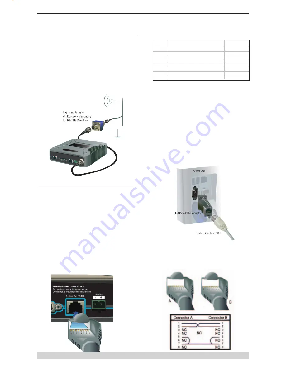
Connecting Antennas and RF Feeders
The RF antenna system should be installed in accordance with the
manufacturers notes.
The RF connector used on the E Series radios are N Type female
connectors. Always use good quality low loss feeder cable,
selected according to the length of the cable run. Ensure all
external connections are waterproofed using amalgamating tape.
Preset directional antennas in the required direction using a
compass, GPS, or visual alignment and ensure correct polarisation
(vertical or horizontal).
Communications Ports
System Port – RJ45
The System Port (available front and rear on EB/EH45e) is a multi-
function interface used for:
•
Programming / Configuration of the radio
•
Remote Diagnostics connections
To access these functions use the TVIEW+ Cable assembly (RJ45
Cable and RJ45 to DB9 Adaptor).
The TVIEW+ Cable is a standard CAT 5 RJ-45 (Male) to RJ-45
(Male) patch cable. It is intended for RS232 serial communications
only and should not be connected directly into an Ethernet port
of a PC. The Cable must be used in conjunction with the RJ-45 to
DB9 Adaptor.
TVIEW+ Adaptor Configuration:
Special user pinouts:
•
Shutdown (Pin 4) - Active low for power save function In
order to put the radio into Shutdown mode, tie pin 4 to a
digital output on a SCADAPack, RTU or similar device.
When it is desired to turn the radio off, switching this digital
output must connect the radio’s pin 4 to ground. The (earth)
ground of both devices would also need to be tied together
as a common reference. (Pin 7 on the radio’s System port)
A 2 wire cable between SCADAPack and radio system port
is all that’s required, with an RJ-45 connector on the radio
end. The Shutdown pin may be left floating for the radio to
remain powered.
•
External PTT (Pin 8) - Provides a manual PTT override
facility for enabling the transmitter. For testing this can be
activated by connecting PTT (Pin 8 ) to Gnd (Pin 7).
System
Port
Description
DB9 Female
Pin 1
System port data out (RS232)
Pin 2
Pin 2
System port data in (RS232)
Pin 3
Pin 3
Factory Use Only - Do not connect No Connection
Pin 4
Shutdown
No Connection
Pin 5
Programming Use Only (Grounded) Pin 5
Pin 6
Factory Use Only - Do not connect No Connection
Pin 7
Ground
Pin 5
Pin 8
External PTT
No Connection
Cross Over cable (Trunking System Port to
System Port)
Some circumstances require a user to trunk the system ports of
two units using an RJ45 cross over cable. Follow the diagram
below to create the cross over cable.


