www.energyabsorption.com
Revision B June 2013
www.highwayguardrail.com
22
All rights in copyright reserved
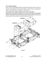
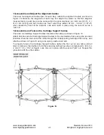
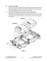
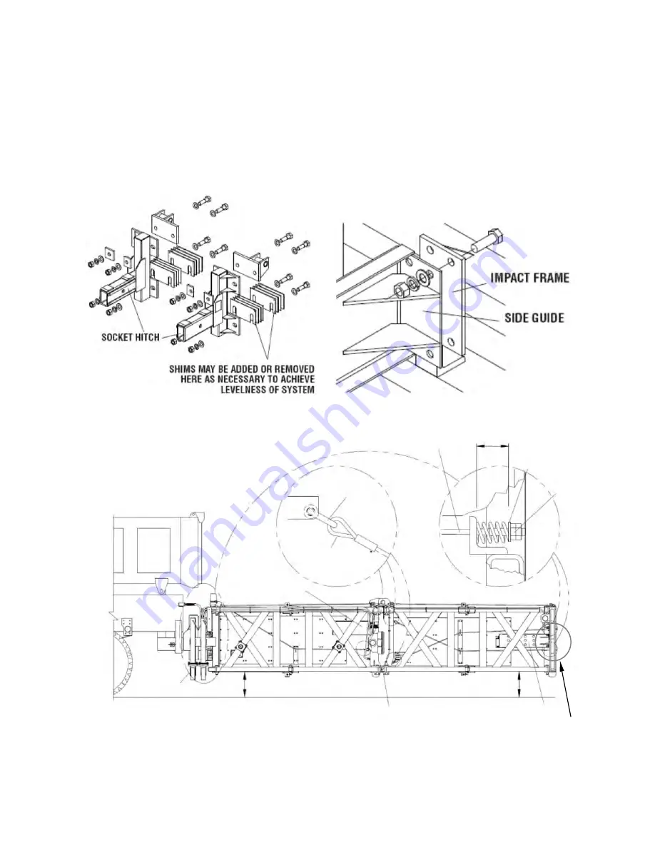
15) Assemble Side Guides
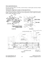
There are four Side Guides, two for Bay 1 and two for Bay 2. Attach guides as shown in Detail
19b and tighten bolts.
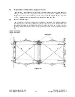
16) Adjust the Height and Levelness of the System Frame
Verify that the system frame is 305±25 mm [12"±1"] from the ground at the front and rear of the
system. It may be necessary to add shims to the Socket Hitch in order to adjust the levelness
of the Cartridge (See Figures 19 & 19a).
Detail 19a
Detail 19b
Figure 19
SEE DETAIL 19a
INTERMEDIATE FRAME
SIDE GUIDE
SEE DETAIL 19b
CARTRIDGE
SUPPORT CABLE
SHACKLE
CARTRIDGE SUPPORT CABLE
32 mm ± 2 mm [1 1/4 ± 1/16]
WASHER
NUTS
305 mm ± 25 mm [12” ± 1]
305 mm ± 25 mm [12” ± 1]

