www.energyabsorption.com
Revision B June 2013
www.highwayguardrail.com
13
All rights in copyright reserved
Preparation
3A) Assembly Must Be Performed On A Level Surface
The system’s framework is very heavy and pivots in several areas. Until the framework is
secured with the cables and trigger bolts, it can swing out in an approximate 4 m [13’] radius
from either side of the truck. A level surface is required to maintain control of the framework
when it is being extended to its full length.
3B) Truck ballast
Use a bubble level to verify that the truck is parked on a level surface. The truck shall be as
close to the final driving weight as possible. If ballast must be added to achieve the 7300 kg
[16,090 lbs.] minimum weight, add it at this time. Ballast must be properly anchored to the truck
to keep it in place during an impact. Ideally, an adequately sized truck, that requires no ballast,
should be used. Because the 943 kg [2080 lbs.] weight of the rearward protruding TMA is
supported by the back of the shadow vehicle, care must be taken not to exceed the
manufacturer's published maximum axle loads. To ensure that the driving characteristics of the
vehicle are maintained, the manufacturer’s recommended center-of-gravity zone shall be
followed completely.
4) Check for interference
Before attempting to assemble the Underride, check for interference concerns.
The System folds such that the Impact Face is very close to the mounting location (See Figure
30 Page 33)
. If you are using something other than a standard Socket Receiver Hitch
Underride refer to special instructions supplied with your assembly then skip to Step 8.
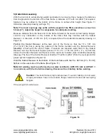
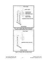
Temporarily position the Underride Socket Receiver under truck frame as shown (See Figure
12) and check for interference concerns. Interference concerns with tail lights, springs, dump
bodies (in the folded or unfolded positions), etc., shall be corrected before proceeding.
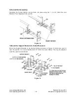
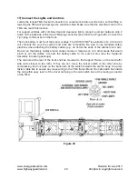
Figure 8


