www.energyabsorption.com
Revision B June 2013
www.highwayguardrail.com
31
All rights in copyright reserved
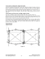
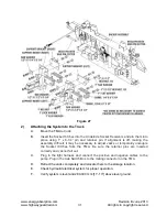
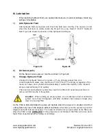
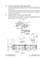
Figure 27
2)
Attaching the System to the Truck
A.
Move the TMA to truck.
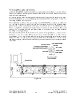
B. Insert
the Socket Hitches into the Underride Socket Receivers and pin them into
place using 1” x 6-1/4” pin and retainer pin. If alignment is off, making the
assembly dif
fi
cult, it may be necessary to adjust Jacks or temporarily uncouple
the Socket Hitches from the TMA. Be sure the retainer pins are inserted
correctly and cannot fall out.
C.
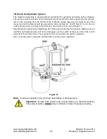
Plug in the light harness and connect the positive and negative cables to the
pump. Plug in the Cab Switch Box to the mating connector on the TMA
.
D.
Retract the Jacks completely and relocate them to the storage location.
E. Check
hydraulic/electrical
system for proper operation.
F.
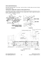
Verify system is level and 280-330 mm [11”-13”] above level ground.

