RTAF-SVX001A-EN
33
Operating Principles
Refrigerant Circuit
Each unit has two refrigerant circuits, with one rotary
screw compressor per circuit. Each refrigerant circuit
includes compressor suction and discharge service
valves, liquid line shut off valve, removable core filter,
liquid line sight glass with moisture indicator, charging
port, high pressure and low pressure safety valve and
electronic expansion valve. Fully modulating compressor
and electronic expansion valve provide variable capacity
modulation over the entire operating range.
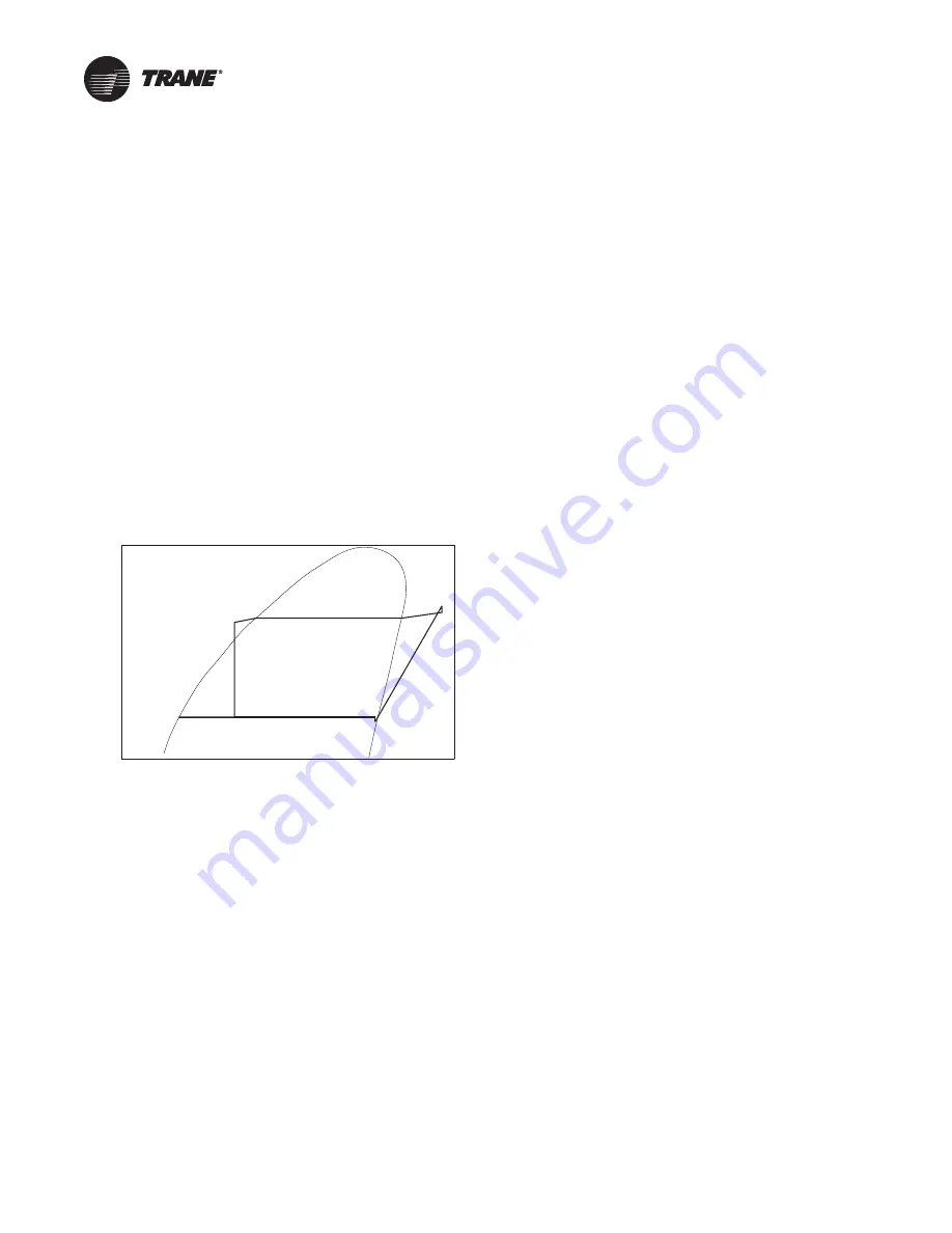
Refrigerant Cycle
Typical refrigerant cycle is represented on the pressure
enthalpy diagram shown in the figure below. Key state
points are indicated on the figure. The cycle for the full
load design point is represented in the plot.
The chiller uses a shell and tube evaporator design with
refrigerant evaporating on the shell side and water flowing
inside tubes having enhanced surfaces (states 4 to 1).The
suction lines are designed to minimize pressure drop
(states 1 to 1b) the compressor is a twin-rotor helical rotary
compressor designed similarly to the compressors
offered in other Trane screw compressor based chiller
(states 1b to 2). The discharge lines include a highly
efficient oil separation system that removes 99.8% of the
oil from the refrigerant stream going to the heat
exchangers (states 2 to 2b). De-superheating, condensing
and sub-cooling are accomplished in a microchannel
cooled heat exchanger where refrigerant is condensed
inside the microchannel (states 2b to 3b). Refrigerant flow
through the system is balanced by an electronic expansion
valve (states 3b to 4).
Refrigerant and Oil
Use only R-134a or R-513A as shown on unit nameplate,
and selected in unit model number digit 16.
Digit 16 =1 or 3: R-513A
Digits 16 = 2 or 4: R-134a
The Sintesis™ chiller uses environmentally friendly
refrigerants. Trane believes that responsible refrigerant
practices are important to the environment, our
customers, and the air conditioning industry. All
technicians who handle refrigerants must be certified.The
Federal Clean Air Act (Section 608) sets forth the
requirements for handling, reclaiming, recovering and
recycling of certain refrigerants and the equipment that is
used in these service procedures. In addition, some states
or municipalities may have additional requirements that
must also be adhered to for responsible management of
refrigerants. Know the applicable laws and follow them.
R-134a and R-513A are medium pressure refrigerants.
They may not be used in any condition that would cause
the chiller to operate in a vacuum without a purge system.
Sintesis is not equipped with a purge system. Therefore,
the chiller may not be operated in a condition that would
result in a saturated condition in the chiller of -15°F (-26°C)
or lower.
Use only the specific POE oil as designated on the unit
nameplate.
Compressor and Lube Oil System
The rotary screw compressor is semi-hermetic, direct
drive, with capacity control via an adaptive frequency
drive, rolling element bearings, differential refrigerant
pressure oil pump and oil heater. The motor is a suction
gas cooled, hermetically sealed, two-pole squirrel cage
induction motor.
Oil separator is provided separate from the compressor.
Oil filtration is provided internal to the compressor. Check
valves in the compressor discharge and lube oil system
are also provided.
Condenser and Fans
The air-cooled microchannel condenser coils use all
aluminum brazed fin construction.The condenser coil has
an integral subcooling circuit. The maximum allowable
working pressure of the condenser is 350 psig.
Condensers are factory proof and leak tested at 525 psig.
Coils can be cleaned with high pressure water.
Direct-drive vertical-discharge airfoil condenser fans are
dynamically balanced. The condenser fan motors are
permanent magnet motors with integrated drive to
provide variable speed fan control for all fans.
Figure 15.
Pressure-enthalphy diagram
R-134a
h (btu/lb)
P (psia)
1
1b
2
2b
3
3b
4
120
140
100
80
60
40
20
0
30
50
100
200
500
600


