Installation
RT-SVX24J-EN
49
Unit Rigging and Placement
1. To configure the unit Center-of-Gravity, utilize TOPSS
or contact the local Trane sales office.
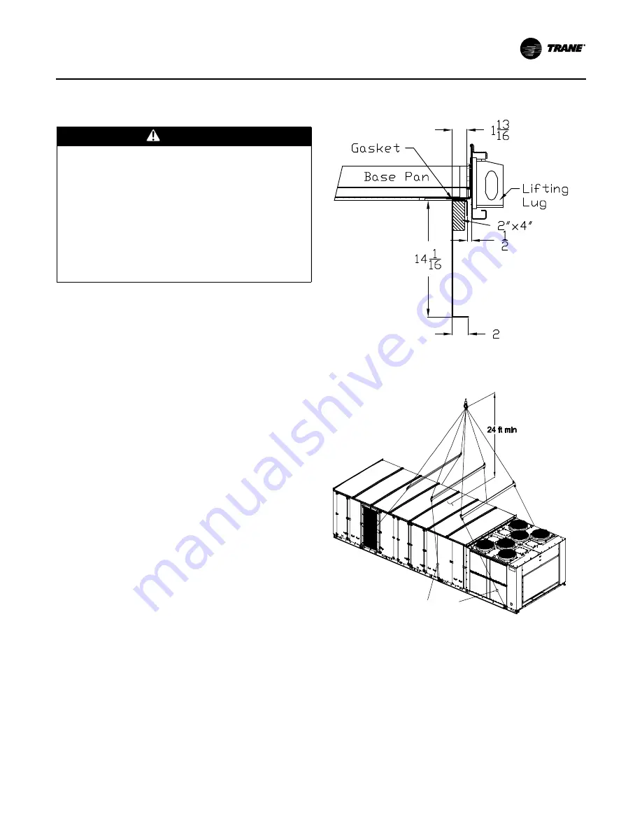
2. Attach adequate strength lifting slings to all lifting lugs.
The figures beginning with
Figure 20, p. 49
show the
minimum distance between the lifting hook and the
top of the unit and illustrate the installation of spreader
bars to protect the unit and to facilitate a uniform lift.
Table 12, p. 42
lists typical approximate minimal unit
operating weights. To determine additional
component weight, see
Table 13, p. 42
3. Test lift the unit to ensure it is properly rigged and
balanced, make any necessary rigging adjustments.
4. Lift the unit and position it over the curb and pedestal.
(These units have a continuous base rail around the air
handler section which matches the curb.
5. Align the base rail of the unit air handler section with
the curb rail while lowering the unit onto the curb.
Make sure that the gasket on the curb is not damaged
while positioning the unit. (The pedestal simply
supports the unit condenser section)
A cross section of the juncture between the unit and the
roof curb is shown in
Figure 19
.
WARNING
Heavy Objects!
Ensure that all the lifting equipment used is properly
rated for the weight of the unit being lifted. Each of the
cables (chains or slings), hooks, and shackles used to
lift the unit must be capable of supporting the entire
weight of the unit. Lifting cables (chains or slings) may
not be of the same length. Adjust as necessary for even
unit lift. Other lifting arrangements could cause
equipment or property damage. Failure to follow
instructions above or properly lift unit could result in
unit dropping and possibly crushing operator/
technician which could result in death or serious injury.
Figure 19. Curb cross section
Figure 20. Typical unit rigging—one-piece unit with three
lifting lugs per side
(a)
One piece unit with three
lifting lugs per side
Turnbuckle or
Chain Adjustment
for each lug


