


LPC-SVX01C-EN
39
installation
procedure
Installation
LPC Unit Corner Weight
Calculations
Calcute model LPC corner weights to
ensure you size isolators correctly.
Remember, units are not internally
isolated and require external isolators
provided at installation.
Before calculating the corner weights,
you must first calculate the total unit
weight. Add the coil, motor, and control
box weights to the main unit weight to
get the total unit weight. Weights are
listed in the Dimensions & Weights
section of this manual.
Example
This example uses a size 8 horizontal
unit, with a right-hand motor/drive &
control box.
Note: Include the wet coil weight. Motor/
drive control box always = 9 lbs.
1. Calculate total LPC operating weight:
component
weight, lbs.
main unit
240
motor, 460/60/3, ½ hp
43
8-row hydronic coil
212.2
control box
9
Total operating weight =
504.2
Reference Figure I-IP-1 for a visual
explanation of the following steps.
2.
Calculate the “leaving air side” corner
weights, labeled C & D in graphic.
•
Divide the main unit weight by 4 to
get main unit corner weight:
240 ÷ 4 = 60 lbs.
•
Divide the motor weight by 2 to get
the 2 corners. Add to the main unit
corner weight to get the total corner
weight: 43 ÷ 2 = 21.5 + 60 = 81.5 lbs.
Note: To get the total corner weight you
must add the motor/drive control box
weight to the correct unit side. See step 4.
3. Calculate the “entering air side”
corner weights, labeled A & B in the
graphic.
•
Divide the coil weight by 2 to get the
2 coil weight corners of the entering
air side. Add to the main unit corner
weight of the entering air side: 212.2
÷ 2 = 106.1 lbs. + 60 lbs. = 166.1 lbs.
Note: To get the total corner weight you
must add the motor/drive control box
weight to the correct unit side. See step 4.
4. Add the motor/drive control box
weight to the correct unit side.
The unit can have the motor/drive control
box on either the right or left-hand side.
Verify this by inspecting the unit or
referencing the unit model number,
digit 12 .
In this example (right-hand motor/drive),
we will add the control box weight to the
leaving air side, corner weight C: 81.5 lbs
+ 9 lbs. = 90.5 lbs.
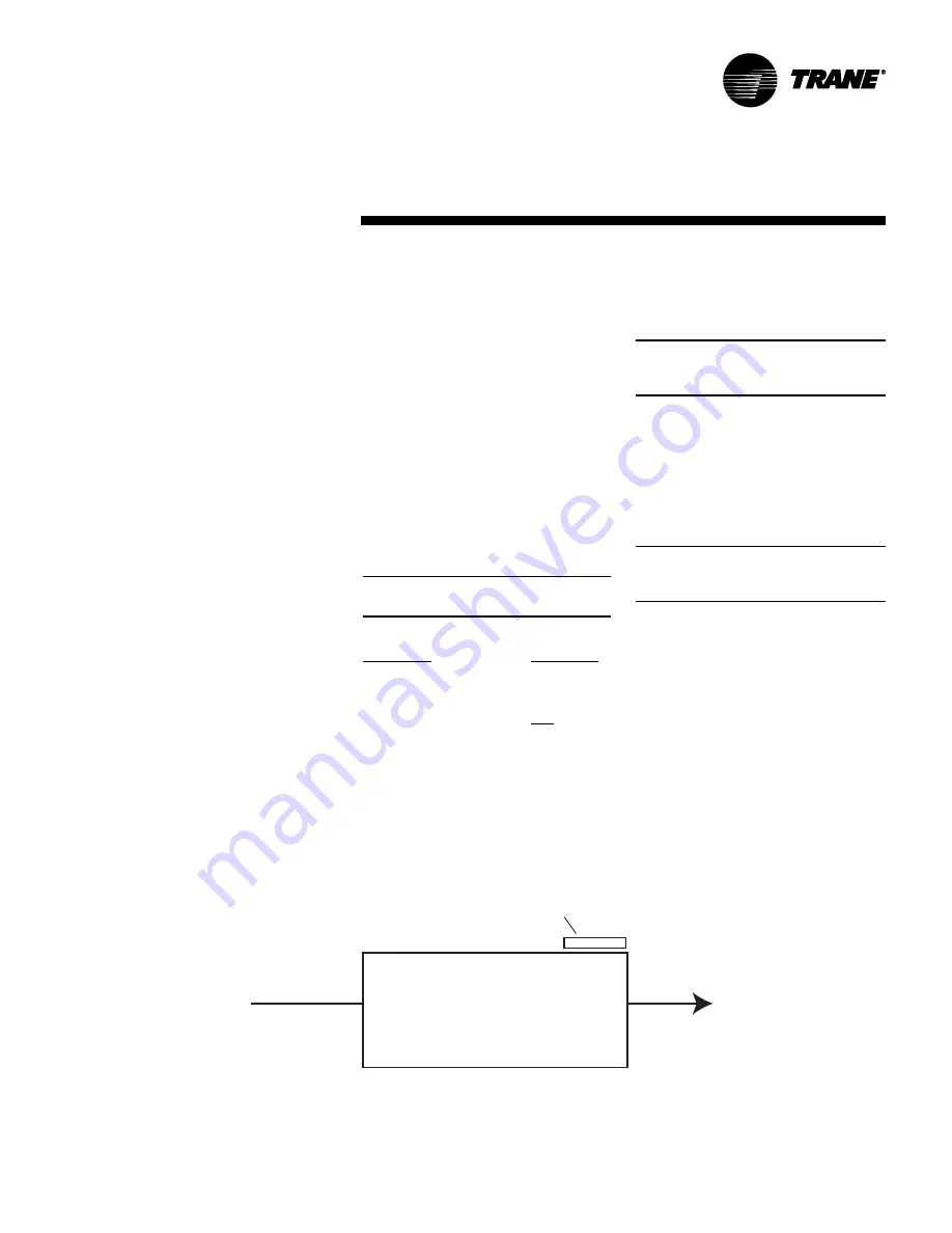
Figure I-IP-1. Corner weight calculation example: size 8 horizontal LPC with a
right-hand motor/drive & control box.
Corner D:
main unit ÷ 4 = 60 lb.
motor ÷ 2 = 21.5 lb.
total corner D = 81.5 lb.
Corner B:
main unit ÷ 4 = 60 lb.
coil ÷ 2 = 106.1 lb.
total corner B = 166.1 lb.
Corner C:
main unit ÷ 4 = 60 lb.
motor ÷ 2 = 21.5 lb.
control box = 9 lb.
total corner C = 90.5 lb.
Corner A:
main unit ÷ 4 = 60 lb.
coil ÷ 2 = 106.1 lb.
total corner A = 166.1 lb.
A
B
C
D
control box
Summary of Contents for LPC
Page 50: ...50 LPC SVX01C EN Operation general information Figure O GI 9 Tracer AH540 termination board ...
Page 91: ...LPC SVX01C EN 91 Maintenance diagnostics Table M D 2 Tracer AH540 541 diagnostics ...
Page 92: ...92 LPC SVX01C EN Maintenance diagnostics Table M D 2 continued Tracer AH540 541 diagnostics ...
Page 94: ...94 LPC SVX01C EN Maintenance troubleshooting Table M T 2 Valves stay open ...
Page 95: ...LPC SVX01C EN 95 Maintenance troubleshooting Table M T 3 Valves stay closed ...
Page 96: ...96 LPC SVX01C EN Maintenance troubleshooting Table M T 4 Outdoor air damper stays open ...
Page 97: ...LPC SVX01C EN 97 Maintenance troubleshooting Table M T 5 Outdoor air damper stays closed ...
Page 107: ...LPC SVX01C EN 107 Maintenance appendix Table M A 6 Hard wired CO2 sensor values ...
Page 109: ......