


CTV-SVX009D-GB
50
4
UNT-PRC002-GB
Technical Data
FWD
08
12
20
30
45
Power supply
(V/Ph/Hz)
230/1/50
Capacities
Cooling capacity on water (1)
(kW)
5,2
8,3
15
18,8
30,1
Heating capacity on water (2)
(kW)
6,3
11,9
18,9
20,9
38,2
Fan motor
(type)
2 x direct drive centrifugal
Fan power input (3)
(kW)
0,23
0,46
0,65
1,04
1,51
Current amps (3)
(A)
1,1
2,2
3,1
4,7
5,5
Start-up amps
(A)
3,2
5,5
9,3
14,1
16,5
Air flow
minimum
(m
3
/h)
490
980
1400
1800
2700
nominal
(m
3
/h)
820
1650
2300
3000
4500
maximum
(m
3
/h)
980
1970
2600
3600
5400
Main coil
Water entering/leaving connections
(type)
ISO R7 rotating female
(Dia)
3/4"
3/4"
1 1/2"
1 1/2"
1 1/2"
Electric heater (accessory for blower only)
Electric power supply
(V/Ph/Hz)
230/1/50
230/1/50 or 400/3/50
400/3/50
400/3/50
400/3/50
Heating capacity
(kW)
2/4
8
10
12
12
Hot water coil (accessory for blower only)
Heating capacity (4)
(kW)
6,3
12
17,4
22,4
34,5
G2 filter (filter box accessory)
Quantity
2
2
2
2
2
Dimensions ( LxWxth)
(mm)
386x221x8
486x271x8
586x321x8
586*421*8
586*621*8
G4 filter (filter box accessory)
Quantity
-
2
2
2
2
Dimensions ( LxWxth)
(mm)
-
486x264x48
586x314x48
586*414*48
586*614*48
Condensate pump (accessory)
(type)
Centrifugal
Water flow - lift height
(l/h - mm)
24 - 500
Not available for FWD30 and FWD45
Sound level (L/M/H speed)
Sound pressure level (5)
(dB(A))
36/40/43
38/41/44
46/50/53
47/52/57
47/52/58
Sound power level (5)
(dB(A))
46/50/53
48/51/54
56/60/63
57/62/67
57/62/68
Unit dimensions
Width x Depth
(mm)
890 x 600
1090 x 710
1290 x 820
1290 x 970
1290 x 1090
Height
(mm)
250
300
350
450
650
Shipped unit dimensions
Width x Depth
(mm)
933 x 644
1133 x 754
1333 x 864
1333 x 1008
1333*1133
Height
(mm)
260
310
360
460
660
Weight
(kg)
32
46
61
76
118
Colour
galvanised steel
Recommended fuse size
Unit alone (aM/gI)
(A)
8/16
8/16
8/16
8/25
8/25
Unit with electric heater (gI)
(A)
16 (2kW),25 (4kW)
40 (230V),3*16 (400V)
3*20
3*25
3*25
(1) Conditions: Water entering/leaving temperature: 7/12 °C, Air inlet temperature 27/19°C DB/WB - Nominal air flow
(2) Conditions: Water entering/leaving temperature: 50/45 °C, Air inlet temperature 20°C DB - Nominal air flow
(3) At high speed with nominal air flow.
(4) Water entering/leaving temperature 90/70 °C, air inlet temperature 20 °C DB, Nominal air flow.
(5) A rectangular glass wool duct 1m50 long is placed on the blower.The measurement is taken in the room containing the blower unit.
Heat exchanger operating limits:
FWD:
*water temperature: max 100° C
*absolute service pressure: min 1 bar/max 11 bars
Accessories - Hot water coil:
*water temperature: min. +2° C/max. 100° C
*absolute service pressure: min 1 bar/max 11 bars
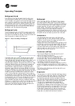
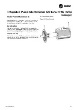
Refrigerant Management
Proper refrigerant charge is essential for proper unit
operation, unit performances, and environmental protection.
Only trained and licensed service personnel should service
the chiller.
Some of the symptoms of a refrigerant under-charged unit:
• Larger-than-normal evaporator approach temperatures
(leaving water temperature – saturated evaporator
temperature). If the refrigerant charge is correct the
approch temperature is between 1°C and 1.5°C on circuit
1 and between 2°C and 2.5°C on circuit 2.These values are
given for units running at full load and with water without
antifreeze
• Low Evaporator-refrigerant temperature limit
• Low Refrigerant-Temperature cutout diagnostic
• Fully-open expansion valve
• Possible whistling sound coming from liquid line
(due to high vapor velocity)
• Possible low discharge superheat at high loads
• High con Subcooler pressure drop
Some of the symptoms of a refrigerant over-charged unit
• Condenser Pressure Limit
• High –Pressure Cutout diagnostic
• More-than-normal number of fans running
• Erratic fan control
R134a/R513A/R1234ze(E) Field –
Charging Procedure
This procedure should be followed when the unit is
empty of all refrigerant and under vacuum. Add the
charge through the evaporator service valve.
1. Respect refrigerant type on the nameplate.
2. Note the weight of the amount of charge removed.
Compare it to the nameplate value. A difference in
charge may indicate a leak.
3. Attach the charging hose to the evaporator service valve
(9mm [3/8inch] flare). Open the service valve.
4. Add charge to the evaporator to bring the total circuit
charge up to the level indicated in the unit nameplate.
5. Close the service valve and disconnect the charging
hose.
Important notice:
-Do not use recycled refrigerant as it may contain oil, which
can affect system reliability. The refrigerant should be pure
and stored in virgin containers
- Hoses should be free of oil
Chiller settings
Prior starting refrigerant charge optimization, the
technician must insure the following chiller conditions:
• Constant water flow on a air purged circuit is strictly
necessary during the whole operation (water fl ow to be
within allowed operating range)
• A fully loaded chiller is highly recommended for a
successful operation. In case the technician is not able
to ensure a 2 circuit fully loaded chiller then he must
lockout one circuit and perform charge optimization for
1 circuit at a time
• When the refrigerant charge optimization is done per
circuit the chiller load must not be lower than 60%
This procedure should be followed when adding
refrigerant to an undercharged unit:
1. Attach the charging hose to the evaporator service
valve (9mm [3/8inch] flare). Open the service valve.
2. Fix the leaving water set point (water temperature to be
steady as much as possible).
3. Adjust water flow within operating range and keep it
steady.
a) Note approach temperature T1
b) Add 2kg of R134a or R1234ze(E) refrigerant
c) Note approach temperature T2
d) If Tn - Tn+1 < 0.2 (with n=1
→
charge addition
count) then charge is good and optimization is done
e) If Tn - Tn+1 > 0.2 (with n=1
→
charge addition
count) then perform steps b) to e) if needed
This procedure should be followed when removing
refrigerant to an overcharged unit:
1. Fix the leaving water set point (water temperature to
be steady as much as possible)
2. Adjust water flow within operating range and keep it
steady
a) Note approach temperature T1
b) Remove 2kg of R134a or R1234ze(E) refrigerant
c) Note approach temperature T2
d) Keep performing step b until Tm+1
- Tm > 0.5 (with m = 1 > charge removal count)
e) Once step d) is confirmed remove 4kg of R134a or
R1234ze(E) refrigerant and note T3
f) If T1-Tn < 0.2 (with n = 3
→
charge removal count)
then charge is good and optimization is done
g) If T1-Tn > (with n = 3
→
charge removal count) then
perform step e) to f) if needed
Periodic Maintenance


