


CTV-SVX009D-GB
29
11
UNT-PRC002-GB
Sound power levels
Discharge
Measurement conditions:
Measurements taken in a room adjacent to the room containing the FWD, at the outlet of the rectangular duct (1.5 m
long) fixed to its discharge opening.
Fan
Power level in dB(A), per Hz frequency band
Overall power
Unit
speed
125
250
500
1000
2000
4000
8000
dB(A)
1
55
50
42
37
37
31
30
46
FWD 08
2
57
54
47
40
30
38
40
50
3
58
57
50
42
32
40
43
53
1
57
51
45
42
34
33
28
48
FWD 10
2
58
54
48
45
38
39
35
51
3
60
58
50
48
40
42
39
54
1
57
51
45
42
34
33
28
48
FWD 12
2
58
54
48
45
38
39
35
51
3
60
58
50
48
40
42
39
54
1
56
62
50
48
39
38
36
56
FWD 14
2
61
66
55
53
47
46
45
60
3
63
69
58
56
50
50
49
63
1
57
63
51
49
40
39
37
57
FWD 20
2
61
66
55
53
47
46
45
60
3
63
69
58
56
50
50
49
63
Intake
Measurement conditions:
Measurements taken at the horizontal air intake.
Fan
Power level in dB(A), per Hz frequency band
Overall power
Unit
speed
125
250
500
1000
2000
4000
8000
dB(A)
1
56
55
55
53
46
45
42
57
FWD 08
2
63
62
60
60
53
53
53
64
3
66
65
63
62
56
55
57
67
1
62
58
55
58
51
48
44
61
FWD 10
2
66
63
60
62
56
55
52
66
3
70
67
63
65
59
59
57
69
1
62
58
55
58
51
48
44
61
FWD 12
2
66
63
60
62
56
55
52
66
3
70
67
63
65
59
59
57
69
1
66
65
65
65
57
50
46
68
FWD 14
2
73
72
69
71
64
59
57
74
3
78
76
73
75
69
64
63
78
1
68
72
64
64
56
52
50
69
FWD 20
2
76
76
68
71
65
61
61
75
3
78
79
71
74
69
66
66
78
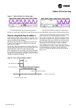
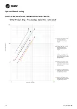
Figure 11 – Total and Partial Free-Cooling option
a.Total Free Cooling, Direct free cooling version
b.Partial Free Cooling, Direct free cooling version
If there is a need to get a definition for partial heat recovery coil distribution, please contact the Trane Sales office.
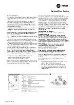
Free-Cooling Enabling Conditions
To get the free cooling active, condition is to have unit in
active cooling mode and that Outdoor temperature low
enough according to figure below.
The free cooling function is enabled when outdoor air
temperature is below Active chilled water cooling set
point minus FC_offset.
A hysteresis should also apply to avoid short cycling of
Free Cooling enabling logic. The Free Cooling offset is an
adjustable parameter to make free cooling active.
If free cooling function is enabled, free cooling becomes
the 1st stage of cooling. Free cooling is the first stage to
engage for cooling capacity loading and the last stage to
consider in capacity unloading.
In order to maximize tandem operation of free cooling
with compressor the following logic is applied:
When unit is configured in “Partial free cooling”, when
free cooling reaches its full capacity and there is a call
for compressor start, then the first circuit to start shall
be circuit 2 (if available).This also means compressor
balancing function is disabled in these conditions.
Note: UC800 will not lockout compressor below free
cooling change over point, but the compressor is locked
out when outdoor air is below “low ambient limit”
set at -10°C. So FC will be the only source of cooling
below -10°C.
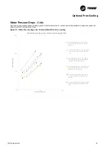
Figure 12 – Free-cooling enabling conditions
Free Cooling Target Offset
Free Cooling Active
Free Cooling Inactive
Outdoor Air Temperature
Chiller Entering Water Temperature
1 deg. C
Free Cooling Activation Target
Optional Free-Cooling


