


CTV-SVX009D-GB
27
11
UNT-PRC002-GB
Sound power levels
Discharge
Measurement conditions:
Measurements taken in a room adjacent to the room containing the FWD, at the outlet of the rectangular duct (1.5 m
long) fixed to its discharge opening.
Fan
Power level in dB(A), per Hz frequency band
Overall power
Unit
speed
125
250
500
1000
2000
4000
8000
dB(A)
1
55
50
42
37
37
31
30
46
FWD 08
2
57
54
47
40
30
38
40
50
3
58
57
50
42
32
40
43
53
1
57
51
45
42
34
33
28
48
FWD 10
2
58
54
48
45
38
39
35
51
3
60
58
50
48
40
42
39
54
1
57
51
45
42
34
33
28
48
FWD 12
2
58
54
48
45
38
39
35
51
3
60
58
50
48
40
42
39
54
1
56
62
50
48
39
38
36
56
FWD 14
2
61
66
55
53
47
46
45
60
3
63
69
58
56
50
50
49
63
1
57
63
51
49
40
39
37
57
FWD 20
2
61
66
55
53
47
46
45
60
3
63
69
58
56
50
50
49
63
Intake
Measurement conditions:
Measurements taken at the horizontal air intake.
Fan
Power level in dB(A), per Hz frequency band
Overall power
Unit
speed
125
250
500
1000
2000
4000
8000
dB(A)
1
56
55
55
53
46
45
42
57
FWD 08
2
63
62
60
60
53
53
53
64
3
66
65
63
62
56
55
57
67
1
62
58
55
58
51
48
44
61
FWD 10
2
66
63
60
62
56
55
52
66
3
70
67
63
65
59
59
57
69
1
62
58
55
58
51
48
44
61
FWD 12
2
66
63
60
62
56
55
52
66
3
70
67
63
65
59
59
57
69
1
66
65
65
65
57
50
46
68
FWD 14
2
73
72
69
71
64
59
57
74
3
78
76
73
75
69
64
63
78
1
68
72
64
64
56
52
50
69
FWD 20
2
76
76
68
71
65
61
61
75
3
78
79
71
74
69
66
66
78
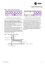
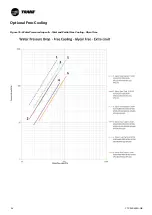
Chiller integrated free-cooling operation
mode
The power of chiller integrated free-cooling relies on
the chiller control to maximize the use of free-cooling
when outdoor temperatures are favorable. The choice
between compressor refrigeration and Free-Cooling
refrigeration will be made and activated depending on
three temperature measurements:
• The ambient air temperature
• The evaporator entering and leaving temperature
• The chilled water set point
Free-cooling coils are fit in series with the evaporator,
and a set of water regulation valves allows the coils
to be by-passed when they are no longer needed due
to outdoor temperatures which are favorable for free-
cooling.
Three operating modes can be differentiated:
1. Summer operation or Compressor refrigeration mode
In this operation mode, ambient temperature is higher
than the temperature of the fluid entering the evaporator.
Free-cooling is not activated, compressors are running, and
control is done in function of the fan/compressor logic of
operation.
2. Mid-season operation or combined refrige Free-
cooling mode
In this operation mode, free-cooling will be enabled
whenever the outdoor temperature is below the evaporator
entering water temperature. The operating logic is described
below. The free-cooling system operates combined with the
mechanical compressor refrigeration. Most of the time, free-
cooling will only partially cover the required cooling duty. In
other words, mechanical refrigeration will complete what
has already been delivered by free-cooling.
3. Winter operation or Full free-cooling mode
Below a certain ambient temperature, and depending on the
chilled water set point requested, the entire cooling duty is
delivered by the free-cooling system. Compressors do not
operate, since the free-cooling coils will be able to deliver
the requested chilled water temperature. The regulation of
the capacity is described in the next section. In this mode,
only fans are running.
General information
The chiller integrated free-cooling system fluid based consist
in a set of “Macro-channels” or “Radiators” coils, fit in the
same frame than the MCHE condenser coils of the chiller
refrigerant circuit. Free-cooling coils will be full aluminum,
flat radiator design type, with low air pressure drop to avoid
fan performances degradation.
Free-cooling coils are fit in series with the evaporator, and a
set of water regulation valves ensures the system to reach
the required free-cooling capacity.
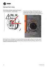
Optional Free-Cooling


