


CTV-SVX009D-GB
46
4
UNT-PRC002-GB
Technical Data
FWD
08
12
20
30
45
Power supply
(V/Ph/Hz)
230/1/50
Capacities
Cooling capacity on water (1)
(kW)
5,2
8,3
15
18,8
30,1
Heating capacity on water (2)
(kW)
6,3
11,9
18,9
20,9
38,2
Fan motor
(type)
2 x direct drive centrifugal
Fan power input (3)
(kW)
0,23
0,46
0,65
1,04
1,51
Current amps (3)
(A)
1,1
2,2
3,1
4,7
5,5
Start-up amps
(A)
3,2
5,5
9,3
14,1
16,5
Air flow
minimum
(m
3
/h)
490
980
1400
1800
2700
nominal
(m
3
/h)
820
1650
2300
3000
4500
maximum
(m
3
/h)
980
1970
2600
3600
5400
Main coil
Water entering/leaving connections
(type)
ISO R7 rotating female
(Dia)
3/4"
3/4"
1 1/2"
1 1/2"
1 1/2"
Electric heater (accessory for blower only)
Electric power supply
(V/Ph/Hz)
230/1/50
230/1/50 or 400/3/50
400/3/50
400/3/50
400/3/50
Heating capacity
(kW)
2/4
8
10
12
12
Hot water coil (accessory for blower only)
Heating capacity (4)
(kW)
6,3
12
17,4
22,4
34,5
G2 filter (filter box accessory)
Quantity
2
2
2
2
2
Dimensions ( LxWxth)
(mm)
386x221x8
486x271x8
586x321x8
586*421*8
586*621*8
G4 filter (filter box accessory)
Quantity
-
2
2
2
2
Dimensions ( LxWxth)
(mm)
-
486x264x48
586x314x48
586*414*48
586*614*48
Condensate pump (accessory)
(type)
Centrifugal
Water flow - lift height
(l/h - mm)
24 - 500
Not available for FWD30 and FWD45
Sound level (L/M/H speed)
Sound pressure level (5)
(dB(A))
36/40/43
38/41/44
46/50/53
47/52/57
47/52/58
Sound power level (5)
(dB(A))
46/50/53
48/51/54
56/60/63
57/62/67
57/62/68
Unit dimensions
Width x Depth
(mm)
890 x 600
1090 x 710
1290 x 820
1290 x 970
1290 x 1090
Height
(mm)
250
300
350
450
650
Shipped unit dimensions
Width x Depth
(mm)
933 x 644
1133 x 754
1333 x 864
1333 x 1008
1333*1133
Height
(mm)
260
310
360
460
660
Weight
(kg)
32
46
61
76
118
Colour
galvanised steel
Recommended fuse size
Unit alone (aM/gI)
(A)
8/16
8/16
8/16
8/25
8/25
Unit with electric heater (gI)
(A)
16 (2kW),25 (4kW)
40 (230V),3*16 (400V)
3*20
3*25
3*25
(1) Conditions: Water entering/leaving temperature: 7/12 °C, Air inlet temperature 27/19°C DB/WB - Nominal air flow
(2) Conditions: Water entering/leaving temperature: 50/45 °C, Air inlet temperature 20°C DB - Nominal air flow
(3) At high speed with nominal air flow.
(4) Water entering/leaving temperature 90/70 °C, air inlet temperature 20 °C DB, Nominal air flow.
(5) A rectangular glass wool duct 1m50 long is placed on the blower.The measurement is taken in the room containing the blower unit.
Heat exchanger operating limits:
FWD:
*water temperature: max 100° C
*absolute service pressure: min 1 bar/max 11 bars
Accessories - Hot water coil:
*water temperature: min. +2° C/max. 100° C
*absolute service pressure: min 1 bar/max 11 bars
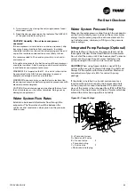
Expansion Tank
(Pump Package Option)
The factory installed expansion tank initial pressure should
be adjusted about 0.5 bars higher than the static pressure
applied to the chiller water inlet. The static pressure is given
by the maximum water circuit height compare to chiller
location: example: the chiller is at ground level and the
circuit loop goes from basement
(at -4m compare to chiller) to third floor at 10 metres above
ground, the static pressure to use is 10 metres of water (1
Bar) and the expansion tank initial pressure should be 1.5
bars.
The expansion tank volume has been selected for typical
loop volume. The following table summarizes the maximum
volume of the chilled water loop that can be supported by
the expansion tank at different conditions. If this maximum
volume versus the required volume of the installation is not
enough, it will be necessary to add an additional expansion
tank located on the low pressure side of the installation.
Table 8 – Maximum water loop volume in function of static
pressure of expansion tank
GVAF 125 - 250
Static pressure
1 Bar
2 Bar
3 Bar
Pure water (l)
6342
3996
1370
Ethylene glycol 20% (l)
3409
2148
736
Ethylene glycol 30% (l)
2273
1432
491
Ethylene glycol 45% (l)
1515
955
327
GVAF 280 - 450
Static pressure
1 Bar
2 Bar
3 Bar
Pure water (l)
9292
5854
2007
Ethylene glycol 20% (l)
5689
3584
1229
Ethylene glycol 30% (l)
4912
3095
1061
Ethylene glycol 45% (l)
4073
2566
880
Tracer UC800 Set-Up
Using Tracer TU service tool, adjust the settings. Refer to
Tracer TU manual and UC800 user guide for instruction on
settings.
CAUTION!
To prevent compressor damage, do not operate
the unit until all refrigerant valves and oil-line service valves
are opened.
IMPORTANT!
A clear sight glass alone does not mean that
the system is properly charged. Also check system discharge
superheat, approach temperature and unit operating
pressures.
Pre-Start Checkout


