


CTV-SVX009D-GB
32
4
UNT-PRC002-GB
Technical Data
FWD
08
12
20
30
45
Power supply
(V/Ph/Hz)
230/1/50
Capacities
Cooling capacity on water (1)
(kW)
5,2
8,3
15
18,8
30,1
Heating capacity on water (2)
(kW)
6,3
11,9
18,9
20,9
38,2
Fan motor
(type)
2 x direct drive centrifugal
Fan power input (3)
(kW)
0,23
0,46
0,65
1,04
1,51
Current amps (3)
(A)
1,1
2,2
3,1
4,7
5,5
Start-up amps
(A)
3,2
5,5
9,3
14,1
16,5
Air flow
minimum
(m
3
/h)
490
980
1400
1800
2700
nominal
(m
3
/h)
820
1650
2300
3000
4500
maximum
(m
3
/h)
980
1970
2600
3600
5400
Main coil
Water entering/leaving connections
(type)
ISO R7 rotating female
(Dia)
3/4"
3/4"
1 1/2"
1 1/2"
1 1/2"
Electric heater (accessory for blower only)
Electric power supply
(V/Ph/Hz)
230/1/50
230/1/50 or 400/3/50
400/3/50
400/3/50
400/3/50
Heating capacity
(kW)
2/4
8
10
12
12
Hot water coil (accessory for blower only)
Heating capacity (4)
(kW)
6,3
12
17,4
22,4
34,5
G2 filter (filter box accessory)
Quantity
2
2
2
2
2
Dimensions ( LxWxth)
(mm)
386x221x8
486x271x8
586x321x8
586*421*8
586*621*8
G4 filter (filter box accessory)
Quantity
-
2
2
2
2
Dimensions ( LxWxth)
(mm)
-
486x264x48
586x314x48
586*414*48
586*614*48
Condensate pump (accessory)
(type)
Centrifugal
Water flow - lift height
(l/h - mm)
24 - 500
Not available for FWD30 and FWD45
Sound level (L/M/H speed)
Sound pressure level (5)
(dB(A))
36/40/43
38/41/44
46/50/53
47/52/57
47/52/58
Sound power level (5)
(dB(A))
46/50/53
48/51/54
56/60/63
57/62/67
57/62/68
Unit dimensions
Width x Depth
(mm)
890 x 600
1090 x 710
1290 x 820
1290 x 970
1290 x 1090
Height
(mm)
250
300
350
450
650
Shipped unit dimensions
Width x Depth
(mm)
933 x 644
1133 x 754
1333 x 864
1333 x 1008
1333*1133
Height
(mm)
260
310
360
460
660
Weight
(kg)
32
46
61
76
118
Colour
galvanised steel
Recommended fuse size
Unit alone (aM/gI)
(A)
8/16
8/16
8/16
8/25
8/25
Unit with electric heater (gI)
(A)
16 (2kW),25 (4kW)
40 (230V),3*16 (400V)
3*20
3*25
3*25
(1) Conditions: Water entering/leaving temperature: 7/12 °C, Air inlet temperature 27/19°C DB/WB - Nominal air flow
(2) Conditions: Water entering/leaving temperature: 50/45 °C, Air inlet temperature 20°C DB - Nominal air flow
(3) At high speed with nominal air flow.
(4) Water entering/leaving temperature 90/70 °C, air inlet temperature 20 °C DB, Nominal air flow.
(5) A rectangular glass wool duct 1m50 long is placed on the blower.The measurement is taken in the room containing the blower unit.
Heat exchanger operating limits:
FWD:
*water temperature: max 100° C
*absolute service pressure: min 1 bar/max 11 bars
Accessories - Hot water coil:
*water temperature: min. +2° C/max. 100° C
*absolute service pressure: min 1 bar/max 11 bars
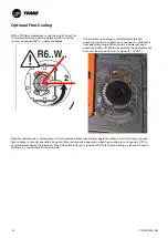
With a Phillips screwdriver, move the end of travel. Fix
it to always keep an opening between 100% and the
minimum desired (50%) in example below.
If the minimum opening is modified after the first
powering, motor re-calibration is needed to validate the
new operating range. When motor is powered, push
green led button (2). Motor memorizes the new reference
of end of travel position on its signal (2…10 VDC)
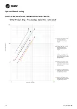
Note for maintenance : Check glycol circuit pressure before free cooling operation season starts. Run glycol pump
few minutes in manual override during monthly maintenance operation when free cooling is continuously OFF to
avoid possible glycol cristalization. Pump Override function is located in TD7 via Button Settings -> Manual Control
Settings -> Free Cooling Pump Override.
Optional Free-Cooling


