Trane GVAF Series Installation Operation & Maintenance Download Page 47

CTV-SVX009D-GB

47

11

UNT-PRC002-GB

Sound power levels

Discharge

Measurement conditions:
Measurements taken in a room adjacent to the room containing the FWD, at the outlet of the rectangular duct (1.5 m
long) fixed to its discharge opening.

Fan

Power level in dB(A), per Hz frequency band

Overall power

Unit

speed

125

250

500

1000

2000

4000

8000

dB(A)

1

55

50

42

37

37

31

30

46

FWD 08

2

57

54

47

40

30

38

40

50

3

58

57

50

42

32

40

43

53

1

57

51

45

42

34

33

28

48

FWD 10

2

58

54

48

45

38

39

35

51

3

60

58

50

48

40

42

39

54

1

57

51

45

42

34

33

28

48

FWD 12

2

58

54

48

45

38

39

35

51

3

60

58

50

48

40

42

39

54

1

56

62

50

48

39

38

36

56

FWD 14

2

61

66

55

53

47

46

45

60

3

63

69

58

56

50

50

49

63

1

57

63

51

49

40

39

37

57

FWD 20

2

61

66

55

53

47

46

45

60

3

63

69

58

56

50

50

49

63

Intake

Measurement conditions:
Measurements taken at the horizontal air intake.

Fan

Power level in dB(A), per Hz frequency band

Overall power

Unit

speed

125

250

500

1000

2000

4000

8000

dB(A)

1

56

55

55

53

46

45

42

57

FWD 08

2

63

62

60

60

53

53

53

64

3

66

65

63

62

56

55

57

67

1

62

58

55

58

51

48

44

61

FWD 10

2

66

63

60

62

56

55

52

66

3

70

67

63

65

59

59

57

69

1

62

58

55

58

51

48

44

61

FWD 12

2

66

63

60

62

56

55

52

66

3

70

67

63

65

59

59

57

69

1

66

65

65

65

57

50

46

68

FWD 14

2

73

72

69

71

64

59

57

74

3

78

76

73

75

69

64

63

78

1

68

72

64

64

56

52

50

69

FWD 20

2

76

76

68

71

65

61

61

75

3

78

79

71

74

69

66

66

78

Unit Start Up Procedures

Daily Unit Start Up 

The timeline for the sequence of operation begins with a 
power-up of the main power to the chiller. The sequence 
assumes 2 circuits, with one or two compressors, Sintesis 
Excellent GVAF chiller with no diagnostics or malfunctioning 
components. External events such as the operator placing 
the chiller in AUTO or STOP, chilled water flow through the 
evaporator, and application of load to the chilled-water loop 
causing loop water-temperature increases, are depicted 
and the chiller responses to those events are shown, with 
appropriate delays noted. The effects of diagnostics, and 
other external interlocks other than evaporator water-flow 
proving, are not considered.
Note: unless the UC800 TD7 and building automation system 
are controlling the chilled-water pump, the manual unit start 
sequence is as follows. Operator actions are noted. 

General 

If the present checkout, as discussed above, has been 
completed, the unit is ready to start.

1.  Press the STOP key on the TD7 display.
2.  As necessary, adjust the set point values on the  

TD7  menus  using Tracer TU. 

3.  Close the fused-disconnect switch for the chilled-water 

pump. Energize the pump(s) to start water circulation 

4.  Check the service valves on the discharge line, suction 

line, oil line, and liquid line for each circuit. These 
valves must be open (back seated) before starting the 
compressors.

5.  Verify that chilled-water pump runs for at least one 

minute after the chiller is commanded to stop (for 
normal chilled-water systems).

6.  Press the AUTO key. If the chiller control calls for cooling, 

and all safety interlocks are closed, the unit will start. The 
compressor(s) will load and unload in response to the 
leaving chilled – water temperature;

After the system has been operating for approximately 30 
minutes and has become stabilized, complete the remaining 
start up procedures, as follows:

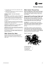
1.  Check the evaporator refrigerant pressure and the 

condenser refrigerant pressure under Refrigerant Report 
on  the TD7. 

2.  Check the EXV sight glasses after enough time has 

elapsed to stabilize the chiller. The refrigerant flow 
through the sight glasses should be clear. Bubbles in 
the refrigerant indicate either low refrigerant charge 
or excessive pressure drop in the liquid line, or an 
expansion valve that is stuck open. A restriction in 
the line can sometimes be identified by a noticeable 
temperature differential between the two sides of the 
restriction. Frost will often form on the line at this point. 
Proper refrigerant charges are shown in the General 
Information Section;

3.  Measure the system discharge superheat.
4.  Clean the air filter located on the door of the control 

panel of AFD if required. 

Note: 

The system cannot be pumped down due to the surge 

characteristics of centrifugal compressors.
Inverted Start, commonly called “Monday Morning Start 
Up”, can be a situation containing a high evaporation 

load (high building heat inertia). This inertia may lead 
to compressor capacity limitations due to choke at low 
pressure ratio.

IMPORTANT NOTICE

- Do not use recycled refrigerant as it may contain oil, which 
can affect system reliability. The refrigerant should be pure 
and stored in virgin containers
- Hoses should be free of oil
- Do not attempt more than three restarts after a critical 
fault. Continued attempts may cause the shaft to 
degmagnetize. Please contact OEM service provider.

Seasonal Unit Startup Procedure

1.  Close all valves and reinstall the drain plugs in the 

evaporator.

2.  Service the auxiliary equipment according to the startup 

and maintenance instructions provided by the respective 
equipment manufacturers. 

3.  Close the vents in the evaporator chilled-water circuits.
4.  Open all the valves in the evaporator chilled-water 

circuits.

5.  Open all refrigerant valves.
6.  If the evaporator was previously drained, vent and fill 

the evaporator and chilled-water circuit. When all air is 
removed from the system (including each pass), install 
the vent plugs in the evaporator water boxes.

7.  Check the adjustment and operation of each safety and 

operating control.

8.  Close all disconnect switches.
9.  Refer to the sequence for daily unit start up for the 

remainder of the seasonal start up.

System Restart after Extended 
Shutdown

1.  Verify that the liquid-line service valves, compressor 

discharge service valves, and optional suction service 
valves are open (back seated)

2.  Fill the evaporator water circuit. Vent the system 

while it is being filled. Open the vent on the top of the 
evaporator while filling, and close it when filling is 
completed. 

3.  Close the fused-disconnect switches that provide power 

to the chilled-water pump.

4.  Start the evaporator water pump and, while water is 

circulating, inspect all piping for leakage. Make any 
necessary repairs before starting the unit.

5.  While the water is circulating, adjust the water flow and 

check the water pressure drops through the evaporator. 
Refer to “water-system flow rates” and “water-system 
pressure drop”

6.  Adjust the flow switch on the evaporator piping for 

proper operation

7.  Stop the water pump. The unit is now ready for startup 

as described “Startup procedures” 

CAUTION!

 To prevent damage to the compressor, ensure that 

all refrigerant valves are open before starting the unit. Do 
not use untreated or improperly treated water. Equipment 
damage may occur.

Summary of Contents for GVAF Series

Page 1: ...SVX009D GB Installation Operation Maintenance GVAF R134a R1234ze R513A Air cooled High Speed Centrifugal Chiller 450 1600 kW April 2020 Confidential and proprietaryTrane information Original instructi...

Page 2: ...1008 1333 1133 Height mm 260 310 360 460 660 Weight kg 32 46 61 76 118 Colour galvanised steel Recommended fuse size Unit alone aM gI A 8 16 8 16 8 16 8 25 8 25 Unit with electric heater gI A 16 2kW...

Page 3: ...ould be carried out only by qualified and experienced personnel 4 To avoid any risk it is recommended to place the unit on an area with limited access Reception On arrival inspect the unit before sign...

Page 4: ...containing the blower unit Heat exchanger operating limits FWD water temperature max 100 C absolute service pressure min 1 bar max 11 bars Accessories Hot water coil water temperature min 2 C max 100...

Page 5: ...6 68 FWD 14 2 73 72 69 71 64 59 57 74 3 78 76 73 75 69 64 63 78 1 68 72 64 64 56 52 50 69 FWD 20 2 76 76 68 71 65 61 61 75 3 78 79 71 74 69 66 66 78 Digit 31 Flow switch X None F Field installed flow...

Page 6: ...ontrol A 506 506 506 506 755 755 755 755 998 998 998 Unit start up amps A 506 506 506 506 755 755 755 755 998 998 998 Unit displacement power factor 0 98 0 98 0 98 0 98 0 98 0 98 0 98 0 98 0 98 0 98 0...

Page 7: ...C motor Airflow per Fan m3 h 19340 19340 20000 20000 20000 20000 20000 20000 20000 20000 20000 Max Power input per Motor kW 1 95 1 95 1 95 1 95 1 95 1 95 1 95 1 95 1 95 1 95 1 95 Max Amps per Motor A...

Page 8: ...Table 2 General Data GVAF 190 350 Extra Efficiency Low Noise and Extra Low Noise R134a R513A GVAF XP 190 205 245 310 350 Cooling Capacity 1 kW 728 19 767 87 883 1117 1243 Unit electrical data 2 3 5 M...

Page 9: ...65 65 65 57 50 46 68 FWD 14 2 73 72 69 71 64 59 57 74 3 78 76 73 75 69 64 63 78 1 68 72 64 64 56 52 50 69 FWD 20 2 76 76 68 71 65 61 61 75 3 78 79 71 74 69 66 66 78 GVAF XP 190 205 245 310 350 Extra L...

Page 10: ...6 689 760 881 961 1001 1121 1242 Unit electrical data 2 3 5 Maximum Power input in cooling kW 254 254 254 254 378 378 378 378 498 498 498 Unit rated amps Max compr Fan Control A 374 374 374 374 557 55...

Page 11: ...2 4 Condenser Fan Quantity 14 14 14 14 20 20 20 20 24 24 24 Diameter mm 800 800 800 800 800 800 800 800 800 800 800 Standard High and Low ambient fan option Fan motor Type Airflow per Fan m3 h 16703 1...

Page 12: ...tions Water entering leaving temperature 7 12 C Air inlet temperature 27 19 C DB WB Nominal air flow 2 Conditions Water entering leaving temperature 50 45 C Air inlet temperature 20 C DB Nominal air f...

Page 13: ...s and automatic modulating valves 8 Provide and install field wiring according to schematics provided in the control panel 9 Install heat tape and insulate the chilled water lines and any other portio...

Page 14: ...avity See instructions on lifting drawings available on request WARNING Heavy Objects Ensure that all the lifting equipment used is properly rated for weight of the unit being lifted Each of the cable...

Page 15: ...ation Requirements Elastomeric Isolators Installation Optional Isolators are ready to install Mountings have to be placed on a rigid and level foundation External equipment should not transmit additio...

Page 16: ...644 1133 x 754 1333 x 864 1333 x 1008 1333 1133 Height mm 260 310 360 460 660 Weight kg 32 46 61 76 118 Colour galvanised steel Recommended fuse size Unit alone aM gI A 8 16 8 16 8 16 8 25 8 25 Unit w...

Page 17: ...ete drainage WaterTreatment In the evaporator the following material are in contact with water Water boxes are made of cast iron GJL250 EN code Tube plates are made of steel P265GH code Tubes are made...

Page 18: ...minal air flow 4 Water entering leaving temperature 90 70 C air inlet temperature 20 C DB Nominal air flow 5 A rectangular glass wool duct 1m50 long is placed on the blower The measurement is taken in...

Page 19: ...64 59 57 74 3 78 76 73 75 69 64 63 78 1 68 72 64 64 56 52 50 69 FWD 20 2 76 76 68 71 65 61 61 75 3 78 79 71 74 69 66 66 78 1 Isolation valve 2 Vibration isolators 3 Evaporator End view 2 pass 4 Evapo...

Page 20: ...50 450 650 Shipped unit dimensions Width x Depth mm 933 x 644 1133 x 754 1333 x 864 1333 x 1008 1333 1133 Height mm 260 310 360 460 660 Weight kg 32 46 61 76 118 Colour galvanised steel Recommended fu...

Page 21: ...least at 10 pipe diameter from discontinuity To read manifold pressure gauges open one valve and close the other depending on the side of the desired reading this eliminate errors resulting from diff...

Page 22: ...450 650 Shipped unit dimensions Width x Depth mm 933 x 644 1133 x 754 1333 x 864 1333 x 1008 1333 1133 Height mm 260 310 360 460 660 Weight kg 32 46 61 76 118 Colour galvanised steel Recommended fuse...

Page 23: ...61 FWD 12 2 66 63 60 62 56 55 52 66 3 70 67 63 65 59 59 57 69 1 66 65 65 65 57 50 46 68 FWD 14 2 73 72 69 71 64 59 57 74 3 78 76 73 75 69 64 63 78 1 68 72 64 64 56 52 50 69 FWD 20 2 76 76 68 71 65 61...

Page 24: ...47 1 47 1 47 1 47 1 47 1 47 1 47 1 47 1 47 1 47 Motor RPM rpm 910 910 910 910 910 910 910 910 910 910 910 Fan type 2 ECXLN ECXLN ECXLN ECXLN ECXLN ECXLN ECXLN ECXLN ECXLN ECXLN ECXLN Power per Motor k...

Page 25: ...rpm 860 860 860 860 860 Input water connection size Grooved coupling in DN 6 150 8 200 Output water connection size Grooved coupling in DN 6 150 8 200 Direct Free Cooling Option Total Free Cooling ty...

Page 26: ...er per Motor kW 1 47 1 47 1 47 1 47 1 47 1 47 1 47 1 47 1 47 1 47 1 47 Motor RPM rpm 910 910 910 910 910 910 910 910 910 910 910 Fan type 2 ECXLN ECXLN ECXLN ECXLN ECXLN ECXLN ECXLN ECXLN ECXLN ECXLN...

Page 27: ...point Free cooling coils are fit in series with the evaporator and a set of water regulation valves allows the coils to be by passed when they are no longer needed due to outdoor temperatures which ar...

Page 28: ...1090 x 710 1290 x 820 1290 x 970 1290 x 1090 Height mm 250 300 350 450 650 Shipped unit dimensions Width x Depth mm 933 x 644 1133 x 754 1333 x 864 1333 x 1008 1333 1133 Height mm 260 310 360 460 660...

Page 29: ...b Partial Free Cooling Direct free cooling version If there is a need to get a definition for partial heat recovery coil distribution please contact theTrane Sales office Free Cooling Enabling Condit...

Page 30: ...090 x 710 1290 x 820 1290 x 970 1290 x 1090 Height mm 250 300 350 450 650 Shipped unit dimensions Width x Depth mm 933 x 644 1133 x 754 1333 x 864 1333 x 1008 1333 1133 Height mm 260 310 360 460 660 W...

Page 31: ...the expansion shall be pressurized at 250 kpa It should be checked when glycol loop is not yet filled or glycol pressure is near zero All Free cooling units must be freeze protected with at least 30 E...

Page 32: ...754 1333 x 864 1333 x 1008 1333 1133 Height mm 260 310 360 460 660 Weight kg 32 46 61 76 118 Colour galvanised steel Recommended fuse size Unit alone aM gI A 8 16 8 16 8 16 8 25 8 25 Unit with electr...

Page 33: ...51 48 44 61 FWD 10 2 66 63 60 62 56 55 52 66 3 70 67 63 65 59 59 57 69 1 62 58 55 58 51 48 44 61 FWD 12 2 66 63 60 62 56 55 52 66 3 70 67 63 65 59 59 57 69 1 66 65 65 65 57 50 46 68 FWD 14 2 73 72 69...

Page 34: ...Sound level L M H speed Sound pressure level 5 dB A 36 40 43 38 41 44 46 50 53 47 52 57 47 52 58 Sound power level 5 dB A 46 50 53 48 51 54 56 60 63 57 62 67 57 62 68 Unit dimensions Width x Depth mm...

Page 35: ...45 60 3 63 69 58 56 50 50 49 63 Intake Measurement conditions Measurements taken at the horizontal air intake Fan Power level in dB A per Hz frequency band Overall power Unit speed 125 250 500 1000 2...

Page 36: ...temperatures Heat tape must be designed for low ambient temperature applications Heat tape selection should be based on the lowest expected ambient temperature c Tracer UC800 controller can start the...

Page 37: ...discharges capacitors Verify with an appropriate voltmeter that all capacitors have discharged DC bus capacitors retain hazardous voltages after input power has been disconnected Follow proper lockou...

Page 38: ...Height mm 260 310 360 460 660 Weight kg 32 46 61 76 118 Colour galvanised steel Recommended fuse size Unit alone aM gI A 8 16 8 16 8 16 8 25 8 25 Unit with electric heater gI A 16 2kW 25 4kW 40 230V 3...

Page 39: ...ovided to each ground connection in the panel CAUTION Customer wiring interface connections are shown in the electrical schematics and connection diagrams that are shipped with the unit The installer...

Page 40: ...r coil water temperature min 2 C max 100 C absolute service pressure min 1 bar max 11 bars Installer Supplied Components The relay output from 1A11 is required to operate the evaporator water pump CHW...

Page 41: ...56 55 55 53 46 45 42 57 FWD 08 2 63 62 60 60 53 53 53 64 3 66 65 63 62 56 55 57 67 1 62 58 55 58 51 48 44 61 FWD 10 2 66 63 60 62 56 55 52 66 3 70 67 63 65 59 59 57 69 1 62 58 55 58 51 48 44 61 FWD 1...

Page 42: ...s having enhanced surfaces state 1 to 2 The vaporized refrigerant flows into the compressor first stage through compressor inlet guide valves The first stage impeller accelerates the vapor increasing...

Page 43: ...FWD 20 2 76 76 68 71 65 61 61 75 3 78 79 71 74 69 66 66 78 Controls Tracer TD7 Operator Interface Controls Overview Sintesis Excellent GVAF units use the following control interface components Tracer...

Page 44: ...terminals and so forth to ensure they are clean and tight 2 Open all refrigerant valves in the discharge liquid and oil return lines 3 Check the power supply voltage to the unit at the main power fuse...

Page 45: ...ator in a humid environment In humid environments the bell housing of the compressor should be insulated A bell housing cover thermal insulator is available as a compressor accessory WARNING It is imp...

Page 46: ...g temperature 90 70 C air inlet temperature 20 C DB Nominal air flow 5 A rectangular glass wool duct 1m50 long is placed on the blower The measurement is taken in the room containing the blower unit H...

Page 47: ...up procedures as follows 1 Check the evaporator refrigerant pressure and the condenser refrigerant pressure under Refrigerant Report on theTD7 2 Check the EXV sight glasses after enough time has elap...

Page 48: ...containing the blower unit Heat exchanger operating limits FWD water temperature max 100 C absolute service pressure min 1 bar max 11 bars Accessories Hot water coil water temperature min 2 C max 100...

Page 49: ...to check operating and safety controls and to inspect electrical components for deficiencies 2 Inspect all piping components for leakage and damage 3 Inspect unit and also areas under isolation 4 Cle...

Page 50: ...its running at full load and with water without antifreeze Low Evaporator refrigerant temperature limit Low Refrigerant Temperature cutout diagnostic Fully open expansion valve Possible whistling soun...

Page 51: ...e evaporator by gravity Low side Charge isolation Procedure After normal shutdown most of the charge resides in the evaporator Running cold water through the evaporator may also drive much of the refr...

Page 52: ...fficient Any breach in the tubes can result in refrigerant leaks Important Only in extreme cases should any type of chemical cleaner or detergent be used on micro channel coils If it becomes absolutel...

Page 53: ...0 dB A 1 56 55 55 53 46 45 42 57 FWD 08 2 63 62 60 60 53 53 53 64 3 66 65 63 62 56 55 57 67 1 62 58 55 58 51 48 44 61 FWD 10 2 66 63 60 62 56 55 52 66 3 70 67 63 65 59 59 57 69 1 62 58 55 58 51 48 44...

Page 54: ...70 C air inlet temperature 20 C DB Nominal air flow 5 A rectangular glass wool duct 1m50 long is placed on the blower The measurement is taken in the room containing the blower unit Heat exchanger ope...

Page 55: ...39 54 1 56 62 50 48 39 38 36 56 FWD 14 2 61 66 55 53 47 46 45 60 3 63 69 58 56 50 50 49 63 1 57 63 51 49 40 39 37 57 FWD 20 2 61 66 55 53 47 46 45 60 3 63 69 58 56 50 50 49 63 Intake Measurement condi...

Page 56: ...on please visit trane com or tranetechnologies com Trane has a policy of continuous product and product data improvement and reserves the right to change design and specifications without notice We ar...

Reviews: