


CTV-SVX009D-GB
42
4
UNT-PRC002-GB
Technical Data
FWD
08
12
20
30
45
Power supply
(V/Ph/Hz)
230/1/50
Capacities
Cooling capacity on water (1)
(kW)
5,2
8,3
15
18,8
30,1
Heating capacity on water (2)
(kW)
6,3
11,9
18,9
20,9
38,2
Fan motor
(type)
2 x direct drive centrifugal
Fan power input (3)
(kW)
0,23
0,46
0,65
1,04
1,51
Current amps (3)
(A)
1,1
2,2
3,1
4,7
5,5
Start-up amps
(A)
3,2
5,5
9,3
14,1
16,5
Air flow
minimum
(m
3
/h)
490
980
1400
1800
2700
nominal
(m
3
/h)
820
1650
2300
3000
4500
maximum
(m
3
/h)
980
1970
2600
3600
5400
Main coil
Water entering/leaving connections
(type)
ISO R7 rotating female
(Dia)
3/4"
3/4"
1 1/2"
1 1/2"
1 1/2"
Electric heater (accessory for blower only)
Electric power supply
(V/Ph/Hz)
230/1/50
230/1/50 or 400/3/50
400/3/50
400/3/50
400/3/50
Heating capacity
(kW)
2/4
8
10
12
12
Hot water coil (accessory for blower only)
Heating capacity (4)
(kW)
6,3
12
17,4
22,4
34,5
G2 filter (filter box accessory)
Quantity
2
2
2
2
2
Dimensions ( LxWxth)
(mm)
386x221x8
486x271x8
586x321x8
586*421*8
586*621*8
G4 filter (filter box accessory)
Quantity
-
2
2
2
2
Dimensions ( LxWxth)
(mm)
-
486x264x48
586x314x48
586*414*48
586*614*48
Condensate pump (accessory)
(type)
Centrifugal
Water flow - lift height
(l/h - mm)
24 - 500
Not available for FWD30 and FWD45
Sound level (L/M/H speed)
Sound pressure level (5)
(dB(A))
36/40/43
38/41/44
46/50/53
47/52/57
47/52/58
Sound power level (5)
(dB(A))
46/50/53
48/51/54
56/60/63
57/62/67
57/62/68
Unit dimensions
Width x Depth
(mm)
890 x 600
1090 x 710
1290 x 820
1290 x 970
1290 x 1090
Height
(mm)
250
300
350
450
650
Shipped unit dimensions
Width x Depth
(mm)
933 x 644
1133 x 754
1333 x 864
1333 x 1008
1333*1133
Height
(mm)
260
310
360
460
660
Weight
(kg)
32
46
61
76
118
Colour
galvanised steel
Recommended fuse size
Unit alone (aM/gI)
(A)
8/16
8/16
8/16
8/25
8/25
Unit with electric heater (gI)
(A)
16 (2kW),25 (4kW)
40 (230V),3*16 (400V)
3*20
3*25
3*25
(1) Conditions: Water entering/leaving temperature: 7/12 °C, Air inlet temperature 27/19°C DB/WB - Nominal air flow
(2) Conditions: Water entering/leaving temperature: 50/45 °C, Air inlet temperature 20°C DB - Nominal air flow
(3) At high speed with nominal air flow.
(4) Water entering/leaving temperature 90/70 °C, air inlet temperature 20 °C DB, Nominal air flow.
(5) A rectangular glass wool duct 1m50 long is placed on the blower.The measurement is taken in the room containing the blower unit.
Heat exchanger operating limits:
FWD:
*water temperature: max 100° C
*absolute service pressure: min 1 bar/max 11 bars
Accessories - Hot water coil:
*water temperature: min. +2° C/max. 100° C
*absolute service pressure: min 1 bar/max 11 bars
Operating Principles
Refrigerant Circuit
Each GVAF unit has two refrigerant circuits, with one or
two centrifugal compressor per circuit. Each refrigerant
circuit includes a compressor suction and discharge service
valve, liquid line shutoff valve, removable core filter, liquid
line sight glass with moisture indicator, charging port and
electronic expansion valve. Fully modulating compressors
and electronic expansion valve provide variable capacity
modulation over the entire operating range.
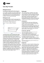
Refrigerant Cycle
Typical refrigerant cycle on the GVAF is represented on the
pressure enthalpy diagram shown in the figure below. Key
state points are indicated on the figure. The cycle for the full
load design point is represented in the plot.
Figure 21 – Pressure enthalpy (P-h) diagram
The GVAF chiller uses a shell and tube evaporator design
with refrigerant evaporating on the shell side and water
flowing inside tubes having enhanced surfaces (state 1 to 2).
The vaporized refrigerant flows into the compressor first
stage through compressor inlet guide valves. The first stage
impeller accelerates the vapor increasing its temperature
and pressure to intermediate state 3. Refrigerant vapor
leaving the first stage compressor is mixed with cooler
refrigerant vapor from the economizer (BPHE). This mixing
lowers the enthalpy of the vapor entering the second stage
to stage 3a. The second stage impeller accelerates the vapor,
further increasing its temperature and pressure to state
point 4. De-superheating, condensing and sub-cooling are
accomplished in a micro channel condenser (state 5 and 5a).
Liquid refrigerant either leaves the micro channel condenser
at point 5a and a part of it flows to the Expansion valve and
enters BPHE economizer at point 6 while the major part
flows to BPHE economizer acting as an additive subcooler.
Refrigerant is cooled down to state 5c and the flow vaporized
goes to the compressor economizer port at state 3.The
major part of the liquid flow goes through the expansion
valve and return to the evaporator at state 1.
Refrigerant
GVAF use R134a / R513A or R1234ze(E), Trane believes
that responsible refrigerant practices are important to
the environment, our customers, and the air conditioning
industry. All technicians who handle refrigerants must be
properly qualified. All local and EU regulations in which
R134a / R513A / R1234ze(E) are specified as medium
pressure refrigerant must be observed. Handling,
reclaiming, recovering and recycling instructions must be
followed. R1234ze(E) requires specific care and dedicated
refrigerant hoses and recovery system have to be used.
Compressor
The centrifugal oil free compressor with frictionless
magnetic bearings is a semi hermetic design with twin
impellers. It has a 3 phase AC voltage input with built in
service inverter for motor speed control.
Compressor control, motor control, motor cooling control
and bearing control are handled by embedded electronics.
Sensor rings check shaft position 8000 times per second
and most of the work is done by permanent magnets while
electromagnets are used to fine tune the shaft position
within less than 10µm of correction.
Condenser and Fans
The air cooled Microchannel condenser coils use all
aluminum brazed fin construction.
The coil is composed of three components: the flat
microchannel tube, the fins located between the
microchannel tubes, and two refrigerant manifolds. Coils
can be cleaned with high pressure water (see Condenser
Coils MCHE maintenance for instructions).
The condenser coil has an integral subcooling circuit. The
maximum allowable working pressure of the condenser is
25.0 bars. Condensers are factory proof and leak tested at 45
bars.
Direct-drive vertical-discharge airfoil condenser fans are
dynamically balanced.
Evaporator
The evaporator is a shell and tube heat exchanger design
constructed from carbon steel shells and tube sheets with
internally and externally finned seamless copper tubes
mechanically expanded into the tube sheets. Tubes are
cleanable with dismountable water boxes. Tubes diameter
exterior is 19mm. Each tube is individually replaceable.
The evaporator is designed, tested and stamped in
accordance with PED 97/23/EC or 2014/68/EU Pressure
regulation for a refrigerant side working pressure of 14 bars.
Standard water connections are grooved for Victaulic style
pipe couplings. Water boxes are available in 1 or 2 passes
configurations according to unit size and include an air
vent, a drain and fittings for temperature control sensors.
Evaporator is insulated with closed cell insulation.


