


CTV-SVX009D-GB
44
4
UNT-PRC002-GB
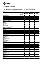
Technical Data
FWD
08
12
20
30
45
Power supply
(V/Ph/Hz)
230/1/50
Capacities
Cooling capacity on water (1)
(kW)
5,2
8,3
15
18,8
30,1
Heating capacity on water (2)
(kW)
6,3
11,9
18,9
20,9
38,2
Fan motor
(type)
2 x direct drive centrifugal
Fan power input (3)
(kW)
0,23
0,46
0,65
1,04
1,51
Current amps (3)
(A)
1,1
2,2
3,1
4,7
5,5
Start-up amps
(A)
3,2
5,5
9,3
14,1
16,5
Air flow
minimum
(m
3
/h)
490
980
1400
1800
2700
nominal
(m
3
/h)
820
1650
2300
3000
4500
maximum
(m
3
/h)
980
1970
2600
3600
5400
Main coil
Water entering/leaving connections
(type)
ISO R7 rotating female
(Dia)
3/4"
3/4"
1 1/2"
1 1/2"
1 1/2"
Electric heater (accessory for blower only)
Electric power supply
(V/Ph/Hz)
230/1/50
230/1/50 or 400/3/50
400/3/50
400/3/50
400/3/50
Heating capacity
(kW)
2/4
8
10
12
12
Hot water coil (accessory for blower only)
Heating capacity (4)
(kW)
6,3
12
17,4
22,4
34,5
G2 filter (filter box accessory)
Quantity
2
2
2
2
2
Dimensions ( LxWxth)
(mm)
386x221x8
486x271x8
586x321x8
586*421*8
586*621*8
G4 filter (filter box accessory)
Quantity
-
2
2
2
2
Dimensions ( LxWxth)
(mm)
-
486x264x48
586x314x48
586*414*48
586*614*48
Condensate pump (accessory)
(type)
Centrifugal
Water flow - lift height
(l/h - mm)
24 - 500
Not available for FWD30 and FWD45
Sound level (L/M/H speed)
Sound pressure level (5)
(dB(A))
36/40/43
38/41/44
46/50/53
47/52/57
47/52/58
Sound power level (5)
(dB(A))
46/50/53
48/51/54
56/60/63
57/62/67
57/62/68
Unit dimensions
Width x Depth
(mm)
890 x 600
1090 x 710
1290 x 820
1290 x 970
1290 x 1090
Height
(mm)
250
300
350
450
650
Shipped unit dimensions
Width x Depth
(mm)
933 x 644
1133 x 754
1333 x 864
1333 x 1008
1333*1133
Height
(mm)
260
310
360
460
660
Weight
(kg)
32
46
61
76
118
Colour
galvanised steel
Recommended fuse size
Unit alone (aM/gI)
(A)
8/16
8/16
8/16
8/25
8/25
Unit with electric heater (gI)
(A)
16 (2kW),25 (4kW)
40 (230V),3*16 (400V)
3*20
3*25
3*25
(1) Conditions: Water entering/leaving temperature: 7/12 °C, Air inlet temperature 27/19°C DB/WB - Nominal air flow
(2) Conditions: Water entering/leaving temperature: 50/45 °C, Air inlet temperature 20°C DB - Nominal air flow
(3) At high speed with nominal air flow.
(4) Water entering/leaving temperature 90/70 °C, air inlet temperature 20 °C DB, Nominal air flow.
(5) A rectangular glass wool duct 1m50 long is placed on the blower.The measurement is taken in the room containing the blower unit.
Heat exchanger operating limits:
FWD:
*water temperature: max 100° C
*absolute service pressure: min 1 bar/max 11 bars
Accessories - Hot water coil:
*water temperature: min. +2° C/max. 100° C
*absolute service pressure: min 1 bar/max 11 bars
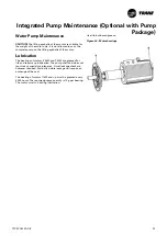
Pre-Start Checkout
Installation Checklist
Complete this checklist as the unit is installed, and verify
that all recommended procedures are accomplished
before the unit is started. This checklist does not replace
the detailed instructions given in the “Installation
Mechanical” and “Installation Electrical” sections of this
manual. In addition, compressor details can be found
in the compressor service documentation. Make sure
to have this documentation prior to any intervention.
Read all sections completely, to become familiar with the
installation procedures, prior beginning the work.
General
When installation is complete, before starting the unit,
the following prestart procedures must be reviewed and
verified:
1. Inspect all wiring connections in the compressor
power circuits (disconnects, terminal block, contactors,
compressor junction box terminals and so forth) to
ensure they are clean and tight.
2. Open all refrigerant valves in the discharge, liquid, and
oil return lines.
3. Check the power-supply voltage to the unit at the main-
power fused-disconnect switch. Voltage must be within
the voltage use range and also stamped on the unit
nameplate. Voltage fluctuation must not exceed 10%.
Voltage imbalance must not exceed 2%
4. Check the unit power phasing L1-L2-L3 in the starter
to ensure that it has been installed in a “A-B-C” phase
sequence.
5. Grounding is essential for the safe operation of the unit :
failure to do so may result in reliability failure
1) Verify continuity of all ground connections.
2) Ensure solid ground connections (both mechanical
and electrical).
3) At one point, usually the entrance of the power supply
panel, all grounds should be connected together
4) All electrical instruments must be rated to 1kVAC and
600VDC. This includes voltage leads and probes.
6. Fill the evaporator chilled-water circuit. Vent the system
while it is being filled. Open the vents on the top of the
evaporator water box while filling and close when filling
is completed.
7. Close the fused-disconnect switch(es) that supplies
power to the chilled-water pump starter.
8. Start the chilled-water pump to begin circulation of
the water. Inspect all piping for leakage and make any
necessary repairs.
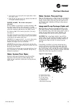
9. With water circulating through the system, adjust the
water flow and check the water pressure drop through
the evaporator.
10. Adjust the chilled-water flow switch for proper operation.
11. Reapply power to complete the procedures
12. Prove all Interlock and Interconnecting Wiring Interlock
and External as described in the Electrical Installation
section.
13. Check and set, as required, all UC800 TD7 menu items.
14. Stop the chilled-water pump.
15. Do not use recycled refrigerant as it may contain oil,
which can affect system reliability. The refrigerant should
be pure and stored in virgin containers
- Hoses should be free of oil
Unit Voltage Power Supply
Unit voltage must meet the criteria given in the
installation Electrical Section. Measure each lead of
the supply voltage at the main power fused-disconnect
switch for the unit. If the measured voltage on any lead
is not within the specified range, notify the supplier of
the power and correct the situation before operating the
unit.
Unit Voltage Imbalance
Excessive voltage imbalance between the phases of a
three-phase system can cause motors to overheat and
eventually fail. The maximum allowable unbalance is
2%. Voltage imbalance is determined using the following
calculations:
% Imbalance = [(Vx – Vave) x 100/Vave]
Vave = (V1 + V2 + V3)/3
Vx = phase with greatest difference from Vave (without
regard to the sign)
Unit Voltage Phasing
It is important that proper rotation of the compressors
be established before the unit is started. Proper motor
rotation requires confirmation of the electrical phase
sequence of the power supply. The motor is internally
connected for clockwise rotation with the incoming
power supply phases A-B-C.
When rotation is clockwise, the phase sequence is
usually called “ABC”, when counterclockwise “CBA”
This direction may be reversed by interchanging any two
of the line wires.
1. Stop the unit from TD7/UC800.
2. Open the electrical disconnect or circuit protection
switch that provides line power to the line power
terminal block(s) in the starter panel (or to the unit
mounted disconnect).
3. Connect the phase-sequence indicator leads to the line
power terminal block as follows;
Phase Sequence Lead
Terminal
Black (Phase A)
L1
Red (Phase B)
L2
Yellow (Phase C)
L3


