background image

18

18-CD20D1-18

Installer’s Guide

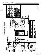
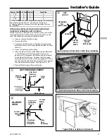
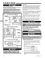
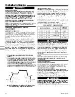
LEFT SIDE PIPING (STANDARD)

TOP VIEW OF RIGHT SIDE PIPING

RIGHT SIDE PIPING (OPTIONAL)

j

WARNING

!

FIRE OR EXPLOSION HAZARD

Failure to follow the safety warnings exactly could result in
serious injury, death or property damage.

Never test for gas leaks with an open flame.  Use a com-
mercially available soap solution made specifically for the
detection of leaks to check all connections.  A fire or
explosion may result causing property damage, personal
injury, or loss of life.
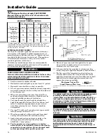
GAS PIPING

This unit is shipped standard for left side installation of gas
piping.  A piping knockout is also provided in the right side
for an alternate piping arrangement.  The installation of
piping shall be in accordance with piping codes and the
regulations of the local gas company.  Pipe joint compound
must be resistant to the chemical reaction with liquefied
petroleum gases.

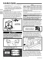
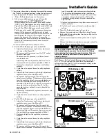
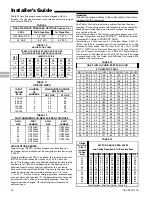
Refer to piping Table 8 for delivery sizes.  Connect gas supply
to the unit, using a ground joint union and a manual shut-off
valve as shown in Figure 27.  National codes require a
condensation drip leg to be installed ahead of the controls as
shown in Figure 27.

The furnace and its individual shut-off valve must be discon-
nected from the gas supply piping system during any pres-
sure testing of that system at test pressures in excess of
1/2 psig.

The furnace must be isolated from the gas supply piping by
closing its individual manual shut-off valve during any
pressure testing of the gas supply piping system at test
pressures equal to or less than 1/2 psig.

CAUTION

!

Use a backup wrench on the gas valve when installing gas
piping to prevent damage to the gas valve and manifold
assembly.

NOTE:
Maximum pressure to the gas valve for natural gas is
13.8" W.C.  Minimum pressure is 5.0" W.C.  Maximum
pressure to the gas valve for propane is 13.8" W.C.
Minimum pressure is 11.0" W.C.

All gas fittings must be checked for leaks using a soapy
solution before lighting the furnace.  DO NOT CHECK WITH
AN OPEN FLAME!

The following warning complies with State of California law, Proposition 65.

Hazardous Gases!

Exposure to fuel substances or by-products of incomplete 
fuel combustion is believed by the state of California to 
cause cancer, birth defects, or other reproductive harm.

WARNING

!

COMBUSTION AND INPUT CHECK

1. Make sure all gas appliances are off except the furnace.

2. Clock the gas meter with the furnace operating (deter-

mine the dial rating of the meter) for one revolution.

3. Match the “Sec” column in the gas flow (in cfh) Table 13

with the time clocked.

4. Read the “Flow” column opposite the number of seconds

clocked.

5. Use the following factors if necessary:

For 1 Cu. Ft. Dial Gas Flow CFH =

Chart Flow Reading ÷ 2

For 1/2 Cu Ft. Dial Gas Flow CFH =

Chart Flow Reading ÷ 4

For 5 Cu. Ft. Dial Gas Flow CFH =

10X Chart Flow Reading ÷ 4

6. Multiply the final figure by the heating value of the gas

obtained from the utility company and compare to the
nameplate rating.  This must not exceed the nameplate
rating.

WARNING

!

TO PREVENT AN EXPLOSION OR POSSIBLE INJURY,
DEATH AND EQUIPMENT DAMAGE, DO NOT STORE
COMBUSTIBLE MATERIALS, GASOLINE OR OTHER
FLAMMABLE VAPORS OR LIQUIDS NEAR THE UNIT.

Summary of Contents for DD060R9V3F Series

Page 1: ...est version USA CANADA ALTERNATE Category I Venting Guide Pub No 18 CH23D1 latest version Horizontal Conversion for these furnaces may be left or right side rotation ALL phases of this installation mu...

Page 2: ...temperature rise and venting according to the manufacturer s instructions 10 This product must be gas piped by a Licensed Plumber or Gas Fitter in the Commonwealth of Massachusetts Safety signal word...

Page 3: ...n these instructions Category I defined on page 13 CAUTION To prevent shortening its service life the furnace should not be used as a Construction Heater during the finishing phases of construction un...

Page 4: ...4 18 CD20D1 18 Installer s Guide From Dwg 21C341699 Rev 4 UD R9V K OUTLINE DRAWING ALL DIMENSIONS ARE IN INCHES...

Page 5: ...wg 21C341700 Sh 1 Rev 0 DD R9V F OUTLINE DRAWING ALL DIMENSIONS ARE IN INCHES MODEL A B C D DD060R9V3F DD080R9V3F 17 1 2 9 5 8 16 1 4 16 DD100R9V5F 21 13 1 16 19 3 4 19 1 2 DD120R9V5F 24 1 2 15 5 16 2...

Page 6: ...looring For vertical downflow application subbase BAYBASE205 must be used between the furnace and combustible flooring When the downflow furnace is installed vertically with a cased coil a subbase is...

Page 7: ...lated caulked vapor barrier etc may need additional air provided as described for con fined space Confined spaces are installations with less than 50 cu ft of space per 1000 BTU hr input from all equi...

Page 8: ...vibration to the annoyance level When the furnace is located in a utility room adjacent to the living area the system should be carefully designed with returns which minimize noise transmission throu...

Page 9: ...ace If only the front of the furnace is accessible it is recom mended that both supply and return air plenums are removable 8 When replacing a furnace old duct work should be cleaned out Thin cloths s...

Page 10: ...ALLATION With the filter removed the filter rack is compressed and then inserted into the bottom of the furnace The retaining screw pin on each side inserts into engagement holes at the bottom of the...

Page 11: ...Leave the bottom panel in place e After the side cutout is made following the directions in the Return Air Duct Connections section on pages 8 and 9 compress the filter rack and reinstall in the side...

Page 12: ...mine the location to be used The furnace cabinet has dimples for location of the alternate furnace clips Side return only Pre drill clearance holes with a 3 16 drill Bottom return holes are pre drille...

Page 13: ...X20X1 13 1 8 24 1 2 2 16X20X1 11 5 8 Location dimension is from end of duct to the screw holes for the bracket VENT PIPING These furnaces have been classified as Fan Assisted Combus tion System Catego...

Page 14: ...other good venting practices as stated in the venting section of the National Fuel Gas Code ANSI Z223 1 latest edition 10 Vent connectors serving appliance vented by natural draft or non positive pre...

Page 15: ...ircuit board must be cut if optional humidistat is used The jumper must also be cut when applying an airflow command signal to the BK input such as with the variable speed single zone and multi zone s...

Page 16: ...ABLE SPEED 2 STAGE FURNACE 1 STAGE HEATING 1 STAGE COOLING USING A 1 STAGE HEATING 1 STAGE COOLING THERMOSTAT OUTDOOR SECTION WITHOUT TRANSFORMER W14 OUTDOOR UNIT NO TRANSFORMER SEE NOTE 6 SEE NOTE 7...

Page 17: ...BK on the circuit board must be cut if an optional Humidistat is installed h HUMIDISTAT HOOKUP If an optional humidistat is to be connected between R and BK the factory installed jumper between R and...

Page 18: ...e gas supply piping system at test pressures equal to or less than 1 2 psig CAUTION Use a backup wrench on the gas valve when installing gas piping to prevent damage to the gas valve and manifold asse...

Page 19: ...times to verify regulator setting e For the White Rodgers gas valve model 36G 1 Adjust low fire by removing the low adjustment regulator cover screw See Figure 29 2 To increase outlet pressure turn th...

Page 20: ...Important Reinstall the propane orifices to the same depth as the orifices supplied with the equipment See Table 14 for help in selecting orifices if orifice change is required Furnace input rate and...

Page 21: ...W1 thermostat contacts close signaling the control module to run its self check routine After the control module has verified that the 1st stage pressure switch contacts are open and the limit switch...

Page 22: ...d gas valve causing shutdown when the door is removed Operation with the door removed or ajar can permit the escape of dangerous fumes All panels must be securely closed at all times for safe operatio...

Page 23: ...ntrol module has shut the system down and gone into lockout the system must be manu ally reset before the unit will restart To reset turn the system power off then on then off and then on again within...

Page 24: ...place IFC Continuous OFF Check Power 2 Flashes System Lockout Retries or Recycles exceeded 3 Flashes Draft Pressure Error Possible problems a Venting problem b Pressure switch problem c Inducer proble...

Reviews: