


18-CD20D1-18
11
Installer’s Guide
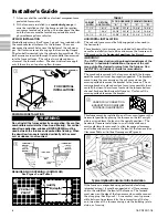
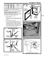
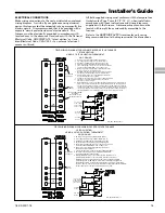
Filter
Rack
Assembly
Furnace
Blower
Deck
Filter Rack
Retaining
Screw/Pin
Engagement Hole
For
Return
Filter Rack
Installation With
Side
Furnace
Cabinet
Side
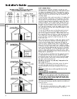
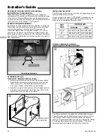
BLOWER
DECK
i
BOTTOM ENGAGEMENT
Bottom Panel
Filter
Rack
Furnace
Cabinet
Side
Filter Rack
Retaining
Screw/Pin
Engagement Hole
For
Bottom Return
Filter Rack
Installation With
u
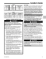
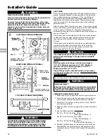
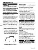
FILTER RACK INSTALLATION FOR SIDE RETURN AIR
ON UPFLOW FURNACES (LEFT OR RIGHT)
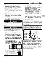
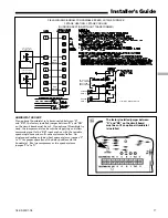
If side air return is desired, it is necessary to move the filter
rack from the bottom of the furnace and reinstall it on the
side. The following instructions should be used:
a. Open or remove the blower door.
b. Remove the filter.
c. Compress the filter rack to disengage the retaining
pins/screws from the furnace sides and slide the filter
rack out.
d. Leave the bottom panel in place.
e. After the side cutout is made following the directions
in the “Return Air Duct Connections” section on
pages 8 and 9; compress the filter rack and reinstall
in the side of the furnace. Confirm that the upper
retaining pin/screw locks into the engagement hole in
the blower deck and the lower pin/screw rests against
the side of the bottom panel. See Figures 14 - 19.
f. Reinstall the furnace filter on the side.
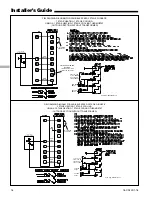
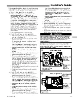
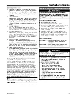
RETAINING
PIN
(Both Sides)
SPRINGS
SIDE
CUTOUT
FILTER
RACK
RAILS
BOTTOM
PANEL
INSTALLED
Airflo
w
Typical Upflow Right Side Return Filter Rack Installation
Airf
low
p
Airflow
a
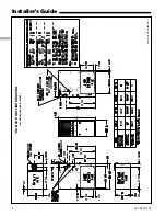
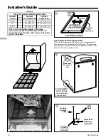
Typical Filters of Upflow in Horizontal
Typical Upflow Left Side Return Filter Rack Installation
o
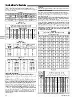
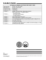
Cabinet Width Left Side Bottom
Right Side
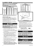
17.5
X
X
X
21
X
X
X
24.5
X
X
X
1. UD060C/R936K0 has 10x7 blower which requires use of alternate
filter clips for left side filter. "K1" and later use the filter rack.
2. Remove bottom front channel to install or reposition filter rack.
X
- All Models


