


18-CD20D1-18
15
Installer’s Guide
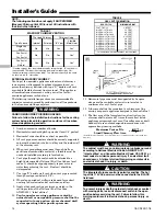
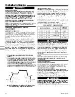
ELECTRICAL CONNECTIONS
Make wiring connections to the unit as indicated on enclosed
wiring diagram. As with all gas appliances using electrical
power, this furnace shall be connected into a permanently live
electric circuit. It is recommended that it be provided with a
separate “circuit protection device” electric circuit. The
furnace must be electrically grounded in accordance with
local codes or in the absence of local codes with the National
Electrical Code, ANSI/NFPA 70 “latest edition” or Cana-
dian Electrical Code, CSA C22.1, if an external electrical
source is utilized.
All field supplied wiring must conform with the temperature
limitation for Type T wire [63° F (35° C)], when installed in
accordance with these instructions and wiring diagrams
supplied with the furnace. A disconnecting means must be
located within sight from, and readily accessible to, the
furnace.
Refer to the SERVICE FACTS literature for unit wiring
diagrams in addition to the diagram inside the blower door.
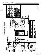
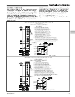
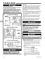
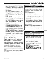
FIELD WIRING DIAGRAMS
1.
Be sure power agrees with equipment nameplates.
2.
Low voltage (24 volt wiring) to be No. 18 A.W.G. min.
3.
Grounding of equipment must comply with local codes.
4.
Set thermostat heat anticipator per unit wiring diagram.
5.
These leads provide 115V. power for connection of electronic
air cleaner and humidifier MAX. load 1.0 amps each.
6.
When a single stage heating thermostat without fan switch
is used, no wiring on "G" terminal is used.
7.
W1 and W2 must be jumpered together for proper operation.
Second stage heat will begin 10 minutes after first stage.
8.
Set dip switches with power off per installation instructions
to set airflow and indoor fan off delays.
9.
Continuous fan airflow can be increased by adding this jumper.
10.
This wire is only for thermostats requiring connection to
transformer common terminal.
11.
Optional humidistat is to be connected between R and BK. Factory installed jumper R
to BK on the circuit board must be cut if optional humidistat is used. The jumper must
also be cut when applying an airflow command signal to the BK input such as with the
variable speed single-zone and multi-zone system controllers. On single speed cooling
only/non-heat pump systems, jumper Y to O for proper operation of the delay profiles
and the humidistat. For two compressor or two speed systems, jumper YLo to O.
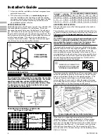
W14
SEE
NOTE 10
SEE
NOTE 9
Y1/Ylo
W14 JUMPER
SEE NOTE 11
FIELD ADDED JUMPER
W1 TO W2.
2ND STAGE WILL FIRE
10 MINUTES AFTER 1ST.
From Dwg. B342027 Rev. 0
SEE
NOTE 6
B/C
B/C
TO 115 V 1 PH.,
60 HZ., POWER
SUPPLY PER
LOCAL CODES
HUM SEE
NOTE 5
EAC SEE
NOTE 5
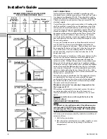
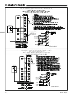
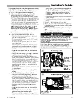
FIELD WIRING DIAGRAM FOR VARIABLE SPEED 2 STAGE FURNACE
1 STAGE HEATING
USING A 1 STAGE HEATING THERMOSTAT
NO COOLING
1. Be sure power agrees with equipment nameplates.
2. Low voltage (24 volt wiring) to be No. 18 A.W.G. min.
3. Grounding of equipment must comply with local codes.
4. Set thermostat heat anticipator per unit wiring diagram.
5. These leads provide 115V. power for connection of electronic
air cleaner and humidifier MAX. load 1.0 amps each.
6. This wire is only for thermostats requiring connection to
transformer common terminal.
7. Continuous fan airflow can be increased by adding this jumper.
8. Set dip switches with power off per installation instructions
to set airflow and indoor fan off delays.
9. Optional humidistat is to be connected between R and BK. Factory
installed jumper R to BK on the circuit board must be cut if optional
humidistat is used. The jumper must also be cut when applying an airflow
command signal to the BK input such as with the variable speed single-zone
and multi-zone system controllers. On single speed cooling only/non-heat pump
systems, jumper Y to O for proper operation of the delay profiles and the humidistat.
For two compressor or two speed systems, jumper YLo to O.
W14
SEE
NOTE 6
From Dwg. B342025 Rev. 0
Y1/Ylo
W14 JUMPER
SEE NOTE 9
SEE
NOTE 7
B/C
B/C
TO 115 V 1 PH.,
60 HZ., POWER
SUPPLY PER
LOCAL CODES
HUM SEE
NOTE 5
EAC SEE
NOTE 5
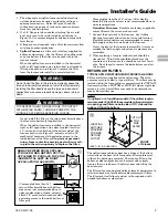
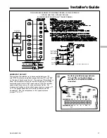
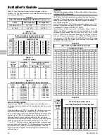
FIELD WIRING DIAGRAM FOR VARIABLE SPEED 2 STAGE FURNACE
2 STAGE HEATING
USING A 2 STAGE HEATING THERMOSTAT
NO COOLING


