


14
18-CD20D1-18
Installer’s Guide
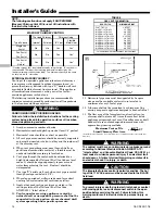
TABLE 7
MASONRY CHIMNEY VENTING
Tile Lined Chimney
Chimney Lining
Type Furnace
Internal
External
“B” Vent
Flexible
Metal Liner
Single Fan
Assist
No
No
Yes
Yes*
Fan Assist
+
Fan Assist
No
No
Yes
Yes*
Fan Assist
+
Natural
Yes
No
Yes
Yes*
* Flexible chimney liner size is determined by using the type “B” vent size for
the available BTUH input, then reducing the maximum capacity by 20%
(multiply maximum capacity times 0.80). The minimum capacity is the same
as shown in the “B” vent tables.
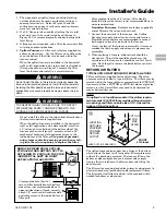
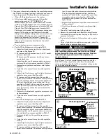
EXTERNAL MASONRY CHIMNEY
Venting of fan assisted appliances into external chimneys
(one or more walls exposed to outdoor temperatures), re-
quires the chimney be lined with type “B”, double wall vent
or suitable flexible chimney liner material. This applies in
all combinations of common venting as well as for fan
assisted appliances vented alone.
The following installation practices are recommended to
minimize corrosion caused by condensation of flue products
in the furnace and flue gas system.
▲
WARNING
!
CARBON MONOXIDE POISONING HAZARD
Failure to follow the installation instructions for the venting
system being placed into operation could result in carbon
monoxide poisoning or death.
1. Avoid an excessive number of bends.
2. Horizontal runs should pitch upward at least 1/4" per foot.
3. Horizontal runs should be as short as possible.
4. All vent pipe or connectors should be securely supported
and must be inserted into, but not beyond the inside wall
at the chimney vent.
5. When vent connections must pass through walls or
partitions of combustible material, a thimble must be
used and installed according to local codes.
6. Vent pipe through the roof should be extended to a
height determined by National Fuel Gas Code or local
codes. It should be capped properly to prevent rain
water from entering the vent. Roof exit should be
waterproofed.
7. Use type “B” double wall vent when vent pipe is routed
through cool spaces (below 60° F.).
8. Where long periods of airflow are desired for comfort,
use long fan cycles instead of continuous airflow.
9. Apply other good venting practices as stated in the
venting section of the National Fuel Gas Code
ANSI Z223.1 “latest edition”.
10.
Vent connectors serving appliance vented by
natural draft or non-positive pressure shall not be
connected into any portion of a mechanized draft
system operating under positive pressure.
11. Horizontal pipe runs must be supported by hangers,
straps or other suitable material in intervals at a
minimum of every 3 feet of pipe.
12. A furnace shall not be connected to a chimney or flue
serving a separate appliance designed to burn solid fuel.
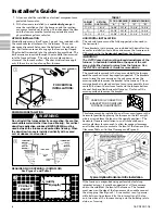
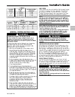
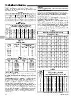
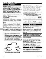
13. The flow area of the largest section of vertical vent or
chimney shall not exceed 7 times the smallest listed
appliance categorized vent area, flue collar area, or draft
hood outlet area unless designed in accordance with
approved engineering methods.
Maximum Vent or Tile
Lined Chimney Flow Area
*Drafthood outlet diameter, flue collar diameter, or listed appliance categorized vent
diameter.
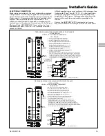
▲
WARNING
!
The cabinet must have an uninterrupted or unbroken ground
according to National Electrical Code, ANSI/NFPA 70 -
“latest edition” and Canadian Electrical Code, CSA C22.1 or
local codes to minimize personal injury if an electrical fault
should occur. A failure to follow this warning could result in
an electrical shock, fire, injury, or death.
▲
CAUTION
!
The integrated furnace control is polarity sensitive. The hot
leg of the 115 VAC power must be connected to the BLACK
field lead.
▲
WARNING
!
To prevent injury or death due to electrical shock or contact
with moving parts, lock unit disconnect switch in the open
position before servicing the unit. Failure to follow this
warning could result in electrical shock, personal injury, or
death.
πππππ
(D*)
2
4
=
X 7
g
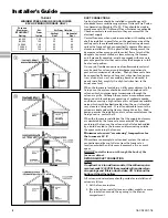
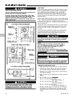
TABLE 8
GAS VENT TERMINATION
ROOF PITCH
MINIMUM HEIGHT
FLAT TO 7/12
OVER 7/12 TO 8/12
OVER 8/12 TO 9/12
OVER 9/12 TO 10/12
OVER 10/12 TO 11/12
OVER 11/12 TO 12/12
OVER 12/12 TO 14/12
OVER 14/12 TO 16/12
OVER 16/12 TO 18/12
OVER 18/12 TO 20/12
OVER 20/12 TO 22/12
1.0 FEET *
1.5 FEET
2.0 FEET
2.5 FEET
3.25 FEET
4.0 FEET
5.0 FEET
6.0 FEET
7.0 FEET
7.5 FEET
8.0 FEET
* THIS REQUIREMENT COVERS MOST INSTALLATIONS
NOTE:
The following section does not apply if BAYVENT800B
(Masonry Chimney Vent Kit) is used. All instructions with
the kit must be followed.


