

20
18-CD20D1-18
Installer’s Guide
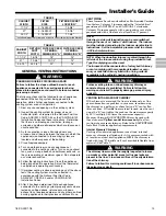
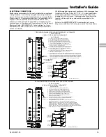
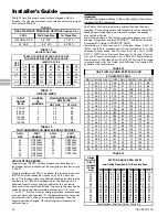
Table 11 lists the main burner orifices shipped with the
furnace. If a change of orifices is required to correct the input
rate, refer to Table 12.
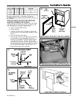
TABLE 9
FINAL MANIFOLD PRESSURE SETTINGS (inches w.c.)
FUEL
2nd Stage Max.
1st Stage Max.
NATURAL GAS
3.5" W.C.
1.7" W.C.
LP GAS
10.5" W.C.
6.0" W.C.
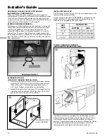
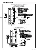
TABLE 10
NATURAL GAS ONLY
TABLE OF CUBIC FEET PER HOUR OF GAS
FOR VARIOUS PIPE SIZES AND LENGTHS
PIPE
SIZE
LENGTH OF PIPE
10
20
30
40
50
60
70
1/2
132
92
73
63
56
50
46
3/4
278
190
152
130
115
105
96
1
520
350
285
245
215
195
180
1-1/4
1050
730
590
520
440
400
370
This table is based on pressure drop of 0.3 inch W.C. and 0.6 SP.GR. gas
TABLE 11
ORIFICE SIZES
INPUT
RATING
BTUH
NUMBER
OF
BURNERS
MAIN BURNER ORIFICE
DRILL SIZE
NAT. GAS
LP GAS
40,000
60,000
80,000
100,000
120,000
140,000
2
3
4
5
6
7
45
45
45
45
45
45
56
56
56
56
56
56
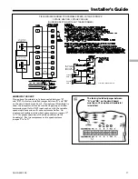
TABLE 12
PART NUMBERS FOR REPLACEMENT ORIFICES
DRILL
SIZE
PART
NUMBER
DRILL
SIZE
PART
NUMBER
44
45
46
47
48
49
50
ORF00501
ORF00644
ORF00909
ORF00910
ORF01099
ORF00503
ORF00493
54
55
56
57
58
59
ORF00555
ORF00693
ORF00907
ORF00908
ORF01338
ORF01339
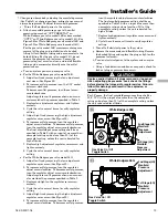
HIGH ALTITUDE DERATE
Input ratings (BTUH) of these furnaces are based on sea
level operation and should not be changed at elevations up to
2,000 ft.
If the installation is 2,000 ft. or above, the furnace input rate
(BTUH) shall be reduced 4% for each 1,000 ft. above sea
level. The furnace input rate shall be checked by clocking the
gas flow rate (CFH) and multiplying by the heating value
obtained from the local utility supplier for the gas being
delivered at the installed altitude. Input rate changes can be
made by adjusting the manifold pressure (min 3.0 - max
3.7 in. W.C. - Natural Gas) or changing orifices (orifice change
may not always be required). If the desired input rate cannot
be achieved with a change in manifold pressure, then the
orifices must be changed. LP installations will require an
orifice change.
Important:
Reinstall the propane orifices to the same depth as the orifices
supplied with the equipment.
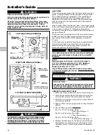
See Table 14 for help in selecting orifices if orifice change is
required. Furnace input rate and temperature rise should be
checked again after changing orifices to confirm the proper
rate for the altitude.
Installations above 4,000 feet may require a pressure switch
change. If required, use the BAYHALT*** Kit (High Altitude
Accessory Kit) listed in PRODUCT DATA.
Installation of this furnace at altitudes above 2,000 ft.
(610m) shall be in accordance with the local codes, or in the
absence of local codes, the
National Fuel Gas Code, ANSI
Z223.1/ NFPA 54
or
National Standard of Canada, Natural
Gas and Propane Installation Code, CSA 149.1
. Installation of
this furnace at altitudes above 2,000 ft. (610m) shall be made
in accordance with the listed high Altitude Conversion Kit
available with this furnace.
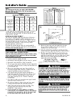
TABLE 13
GAS FLOW IN CUBIC FEET PER HOUR
2 CUBIC FOOT DIAL
SEC. FLOW
SEC. FLOW
SEC. FLOW
SEC. FLOW
8
900
29
248
50
144
82
88
9
800
30
240
51
141
84
86
10
720
31
232
52
138
86
84
11
655
32
225
53
136
88
82
12
600
33
218
54
133
90
80
13
555
34
212
55
131
92
78
14
514
35
206
56
129
94
76
15
480
36
200
57
126
96
75
16
450
37
195
58
124
98
73
17
424
38
189
59
122
100
72
18
400
39
185
60
120
104
69
19
379
40
180
62
116
108
67
20
360
41
176
64
112
112
64
21
343
42
172
66
109
116
62
22
327
43
167
68
106
120
60
23
313
44
164
70
103
124
58
24
300
45
160
72
100
128
56
25
288
46
157
74
97
132
54
26
277
47
153
76
95
136
53
27
267
48
150
78
92
140
51
28
257
49
147
80
90
144
50
TABLE 14
Orifice
Twist Drill
Size If
Installed
At Sea
Level
ALTITUDE ABOVE SEA LEVEL
and Orifice Required At Other Elevations
2000 3000 4000 5000 6000 7000 8000 9000 10000
42
43
44
45
46
47
42
44
45
46
47
48
43
44
45
47
47
48
43
44
45
47
47
49
43
45
46
47
48
49
44
45
47
48
48
49
44
46
47
48
49
50
45
47
48
49
49
50
46
47
48
49
50
51
47
48
50
50
51
52
54
55
56
57
58
54
55
56
58
59
55
55
56
59
60
55
55
57
59
60
55
56
57
60
61
55
56
57
60
62
55
56
58
61
62
56
56
59
62
63
56
56
59
63
63
56
57
60
63
64
From National Fuel Gas Code - Table F-4


