


18-CD20D1-18
17
Installer’s Guide
W14
OUTDOOR UNIT NO. 2
(NO TRANSFORMER)
OUTDOOR UNIT NO. 1
(NO TRANSFORMER)
SEE NOTE 3
SEE
NOTE 6
SEE
NOTE 7
From Dwg. B342018 Rev. 0
B/C
B/C
TO 115 V 1 PH.,
60 HZ., POWER
SUPPLY PER
LOCAL CODES
HUM SEE
NOTE 5
EAC SEE
NOTE 5
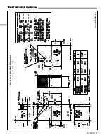
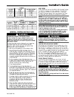
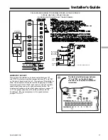
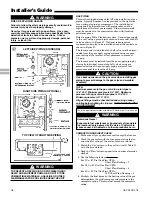
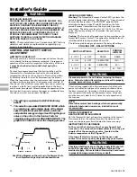
FIELD WIRING DIAGRAM FOR VARIABLE SPEED 2 STAGE FURNACE
2 STAGE HEATING, 2 STAGE COOLING
(OURDOOR SECTION WITHOUT TRANSFORMER)
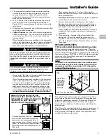
The factory installed jumper between
“R” and “BK” on the circuit board
must be cut if an optional Humidistat
is installed.
h
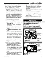
HUMIDISTAT HOOKUP
If an optional humidistat is to be connected between “R”
and “BK”, the factory installed jumper between “R” and “BK”
on the circuit board must be cut. If an optional Humidistat is
used, the jumper must also be cut when applying an airflow
command signal to the “BK” input such as with the variable
speed single-zone and multi-zone system controller. On
single speed cooling only/non-heat pump systems, jumper “Y”
to “O” for proper operation of the delay profiles and the
humidistat. For two compressor or two speed systems,
jumper “Ylo” to “O”.


