


6
18-CD20D1-18
Installer’s Guide
123456789012345678901234567890121234567890123456
123456789012345678901234567890121234567890123456
123456789012345678901234567890121234567890123456
123456789012345678901234567890121234567890123456
123456789012345678901234567890121234567890123456
123456789012345678901234567890121234567890123456
123456789012345678901234567890121234567890123456
123456789012345678901234567890121234567890123456
123456789012345678901234567890121234567890123456
123456789012345678901234567890121234567890123456
123456789012345678901234567890121234567890123456
123456789012345678901234567890121234567890123456
123456789012345678901234567890121234567890123456
123456789012345678901234567890121234567890123456
123456789012345678901234567890121234567890123456
123456789012345678901234567890121234567890123456
123456789012345678901234567890121234567890123456
123456789012345678901234567890121234567890123456
123456789012345678901234567890121234567890123456
123456789012345678901234567890121234567890123456
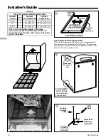
FURNACE
FRONT
A (width)
B (depth)
C
D
3
UP
FL
OW
FU
RN
AC
E
CASED
COIL
SCREWS
(BOTH SIDES)
STANDOFFS
(BOTH SIDES)
STANDOFFS (4)
DRILL SCREWS (4)
FOR VERTICAL
INSTALLATIONS:
1
2
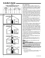
7. A furnace shall be installed so electrical components are
protected from water.
8. If the furnace is installed in a
residential garage
, it
must be installed so that the burners, and the ignition
source are located not less than 18 inches above the floor
and the furnace must be located or protected to avoid
physical damage from vehicles.
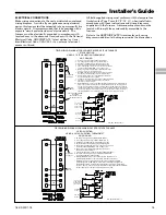
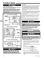
UPFLOW INSTALLATION
Standoffs and screws (See Figure 1, page 6) are included with
the cased coils for attachment to the furnace. There are
clearance alignment holes near the bottom of the coil wrap-
per. Drill screws are used to engage the furnace top flanges.
The standoff is inserted into the cabinet alignment hole. The
drill screws are inserted through the standoffs then screwed
into the furnace flange. The coil is always placed down-
stream of the furnace airflow. The above instructions apply
only if the coil is on top of an upflow furnace.
DOWNFLOW INSTALLATION
▲
WARNING
!
Do not install the furnace directly on carpeting, tile or other
combustible material other than wood flooring. For vertical
downflow application, subbase (BAYBASE205) must be
used between the furnace and combustible flooring. When
the downflow furnace is installed vertically with a cased
coil, a subbase is not required.
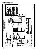
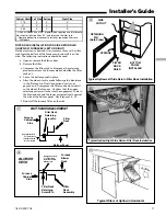
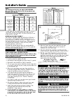
REQUIRED FLOOR OPENING: (DOWNFLOW)
See Figure 3 and Table 1
TABLE 1
CABINET
WIDTH
RETURN
DUCT WIDTH
FLOOR OPENING PLENUM OPENING
"A"
"B"
"C"
"D"
17-1/2"
16-1/4"
16-5/8"
20-1/8"
15-5/8"
19-3/8"
21"
19-3/4"
20-1/8"
20-1/8"
19-1/8"
19-3/8"
24-1/2"
23-1/4"
23-5/8"
20-1/8"
22-5/8"
19-3/8"
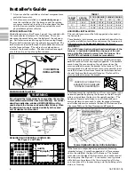
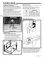
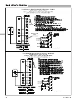
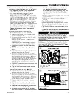
HORIZONTAL INSTALLATION
The coil and furnace must be fully supported when used in
the horizontal.
Three brackets (with screws) are included with downflow fur-
naces for installation to stabilize and secure the furnace and
TXC cased coil in the
horizontal position
. See Figure 4.
IMPORTANT:
The 2/4TXC cased coil must be placed downstream of the
furnace. In horizontal installations, the apex of the coil
may point either toward or away from the furnace. See
the 2/4TXC coil Installer's Guide for more details.
The cased coil is secured to the furnace and both the furnace
and
the cased coil must be properly supported. The brackets
mount using the rear screws on the coil case and use the
screws provided to secure the bracket to the furnace. The re-
maining bracket is placed as close to center as possible (hori-
zontally) between the coil case front and the furnace bottom
channel (for downflow/horizontal furnace). Use four of the
screws provided to secure the bracket.
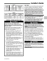
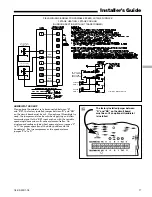
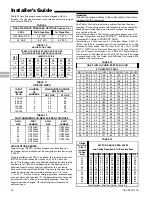
This furnace may be installed in an attic or crawl space in the
horizontal position by placing the furnace on the left or right
side (as viewed from the front in the upright position). The
horizontal furnace installation in an attic should be on a
service platform large enough to allow for proper clearances
on all sides and service access to the front of the furnace (See
Clearance Table on Outline Drawings and Figure 5).
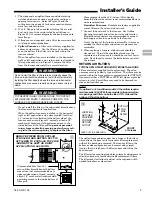
If the furnace is suspended using perforated steel strap
(plumber’s strap), it must be supported at all four corners
and in the middle at the front of the furnace. The forward
most screw on the side of the furnace may be used to connect
the strapping (See Figure 5). Line contact is only permis-
sible between lines formed by the intersection of the top
and two sides of the furnace casing and the building joists,
studs, or framing.
CASED COIL CONNECTION
BRACKET FOR DOWNFLOW
FURNACE IN HORIZONTAL
4
5
Typical Upflow/Horizontal Attic Installation


