


18-CD20D1-18
3
Installer’s Guide
Installation Instructions
3
General Installation Instructions
3
Location and Clearances
3
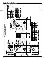
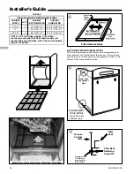
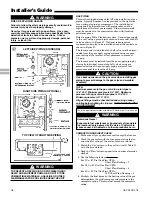
Outline Drawing
4-5
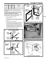
Upflow Installation
6
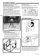
Downflow Installation
6
Horizontal Installation
6
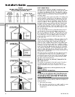
Air for Combustion and Ventilation
7
Duct Connections
8
Return Air Filters
9-13
General Venting Instructions
13
Venting into a Masonry Chimney
13
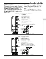
Electrical Connections
15
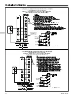
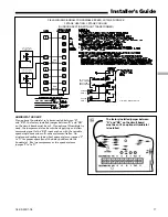
Field Wiring Diagrams
15-17
Gas Piping
18
Combustion and Input Check
18
High Altitude Derate
20
Start Up and Adjustment
21
Preliminary Inspections
21
Lighting Instructions
21
Sequence Of Operation
21
Control and Safety Switch Adjustment
22
Abnormal Conditions
23
IFC Error Flash Codes
24
Contents
GENERAL INSTALLATION INSTRUCTIONS
The manufacturer assumes no responsibility for equipment
installed in violation of any code or regulation.
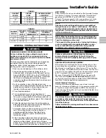
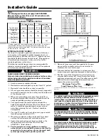
It is recommended that Manual J of the Air Conditioning
Contractors Association (ACCA) or A.R.I. 230 be followed in
estimating heating requirements. When estimating heating
requirements for installation at Altitudes above 2000 ft.,
remember the gas input must be reduced (See GAS INPUT
ADJUSTMENT).
Material in this shipment has been inspected at the
factory and released to the transportation agency
without known damage. Inspect exterior of carton for
evidence of rough handling in shipment. Unpack
carefully after moving equipment to approximate
location. If damage to contents is found, report the
damage immediately to the delivering agency.
Codes and local utility requirements governing the installa-
tion of gas fired equipment, wiring, plumbing, and flue
connections must be adhered to. In the absence of local codes,
the installation must conform with latest edition of the
National Fuel Gas Code ANSI Z223.1 • National Installation
Code, CAN/CGA B149.1. The latest code may be obtained
from the American Gas Association Laboratories, 400 N.
Capitol St. NW, Washington D.C. 20001.
1-800-699-9277 or www.aga.org
These furnaces have been classified as Fan Assisted
Combustion system CATEGORY I furnaces as required by
ANSI Z21.47 “latest edition” and CAN/CGA 2.3. Therefore
they do not require any special provisions for venting other
than what is indicated in these instructions. (Category I
defined on page 13).
▲
CAUTION
!
To prevent shortening its service life, the furnace should not
be used as a “Construction Heater” during the finishing
phases of construction until the requirements listed in item
9, a-g of the safety section of this publication have been met.
Condensate in the presence of chlorides and fluorides from
paint, varnish, stains, adhesives, cleaning compounds, and
cement create a corrosive condition which may cause rapid
deterioration of the heat exchanger.
▲
CAUTION
!
Do not install the furnace in a corrosive or contaminated
atmosphere.
▲
WARNING
!
These furnaces are not approved or intended for installation
in manufactured (mobile) housing, trailers, or recreational
vehicles. Failure to follow this warning could result in
property damage, personal injury, or death.
▲
WARNING
!
Do not install the furnace directly on carpeting, tile or other
combustible material other than wood flooring. For vertical
downflow application, subbase (BAYBASE205) must be
used between the furnace and combustible flooring. When
the downflow furnace is installed vertically with a cased coil,
a subbase is not required.
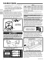
LOCATION AND CLEARANCES
The location of the furnace is normally selected by the
architect, the builder, or the installer. However, before the
furnace is moved into place, be sure to consider the following
requirements:
1. Is the location selected as near the chimney or vent and
as centralized for heat distribution as practical?
2. Do all clearances between the furnace and enclosure
equal or exceed the minimums stated in Clearance Table
on the Outline Drawings.
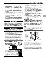
3. Is there sufficient space for servicing the furnace and
other equipment? A minimum of 24 inches front accessi-
bility to the furnace must be provided. Any access door
or panel must permit removal of the largest component.
4. Are there at least 3 inches of clearance between the
furnace combustion air openings in the front panel and
any closed panel or door provided?
5. Are the ventilation and combustion air openings large
enough and will they remain unobstructed? If outside
air is used, are the openings set above the highest snow
accumulation level? (See the Air for Combustion and
Ventilation section.)
6. Allow sufficient height in supply plenum above the
furnace to provide for cooling coil installation, if the
cooling coil is not installed at the time of this furnace
installation.


