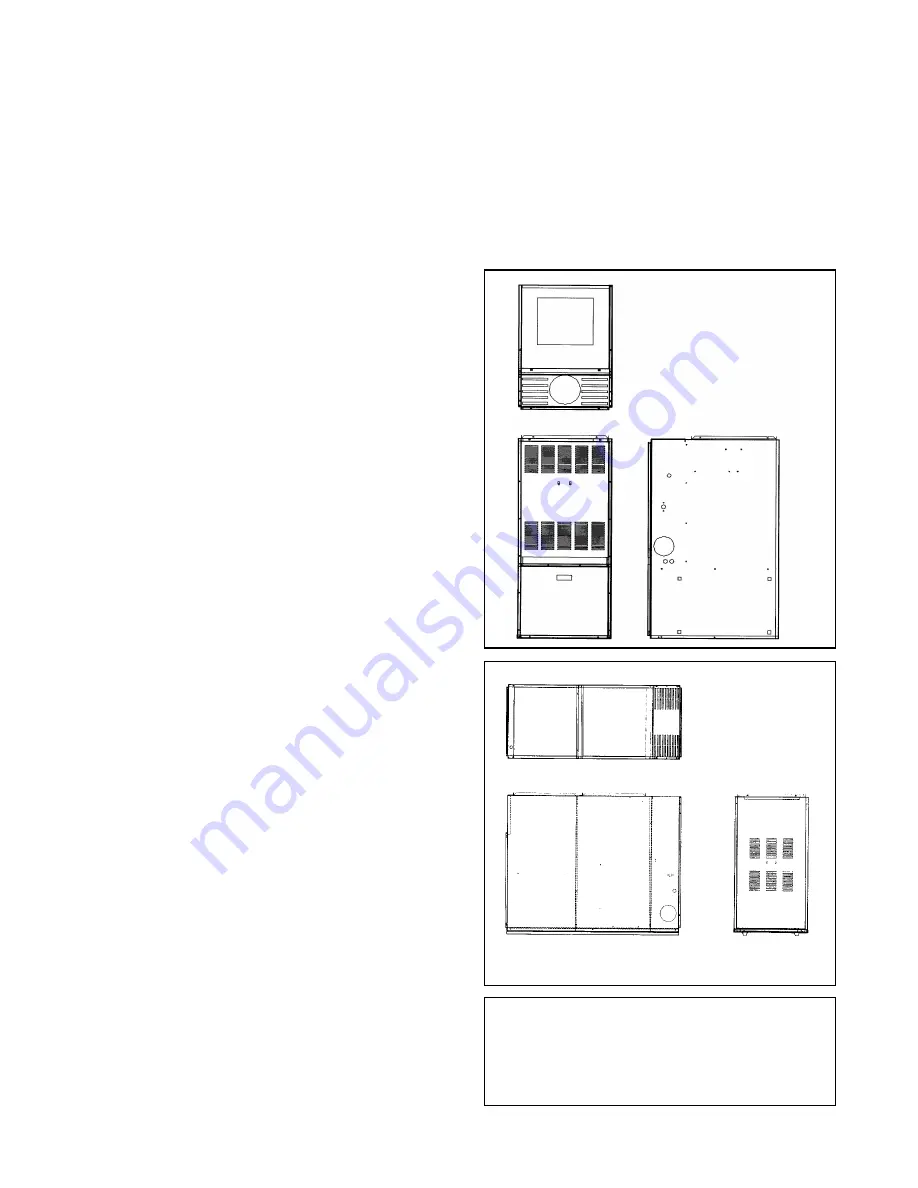
background image


OIL-FIRED WARM AIR 

FURNACE 

P2HMX12F08001   P3HMX14F10001 

P3HMX20F12001 

(Upflow or Horizontal Models) 

P3LBX12F08001   P3LBX14F12001 

(Lowboy Models)


INTRODUCTION ...............................................................2


HEAT LOSS ......................................................................2


LOCATION OF UNIT ........................................................2


AIR CONDITIONING .........................................................4


COMBUSTION AIR ...........................................................4


CHIMNEY VENTING .........................................................4


OIL TANK..........................................................................6


PIPING INSTALLATION ...................................................6


ELECTRICAL CONNECTIONS ........................................6


CIRCULATING AIR BLOWER..........................................7


OIL BURNER ....................................................................8


FURNACE INSTALLATION SET-UP................................9


MAINTENANCE AND SERVICE.....................................10


OPERATING INSTRUCTIONS .......................................10


TABLE A-1: BECKETT OIL BURNER SET-UP .............11


TABLE A-2: DIRECT DRIVE BLOWER SET-UP ...........11


TABLE A-3: DIRECT DRIVE BLOWER 
CHARACTERISTICS ......................................................12


GENERAL DIMENSIONS – P*HMX MODELS ...............14


GENERAL DIMENSIONS – P3LBX MODELS................15


APPENDIX B: WIRING DIAGRAM .................................16


WIRING NOTES..............................................................17


R7184 DETAILED SEQUENCE OF OPERATION..........18


TABLE C-1: ST9103 DETAILED SEQUENCE OF 
OPERATION ...................................................................20


TABLE C-2:  CAD CELL RESISTANCE ........................21


TABLE C-3:  R7184 TROUBLESHOOTING...................21


TABLE C-4:  SYSTEM AND GENERAL 
TROUBLESHOOTING ....................................................24


AIR FILTER LOCATIONS...............................................27


REPAIR PART LIST – P3HMX14F10001 & 
P3HMX20F12001 ............................................................28


REPAIR PART LIST – P3LBX12F08001A & 
P3LBX14F12001A ..........................................................29


REPAIR PART LIST – P2HMX12F08001 .......................30


REPLACEMENT PART CONTACT INFORMATION ......31


INSTALLATION

MANUAL 


CONTENTS 

Read this manual completely before beginning
installation. 
Important: These instructions must be kept with
the furnace for future reference. 

Summary of Contents for P2HMX12F08001

Page 1: ... DRIVE BLOWER CHARACTERISTICS 12 GENERAL DIMENSIONS P HMX MODELS 14 GENERAL DIMENSIONS P3LBX MODELS 15 APPENDIX B WIRING DIAGRAM 16 WIRING NOTES 17 R7184 DETAILED SEQUENCE OF OPERATION 18 TABLE C 1 ST9103 DETAILED SEQUENCE OF OPERATION 20 TABLE C 2 CAD CELL RESISTANCE 21 TABLE C 3 R7184 TROUBLESHOOTING 21 TABLE C 4 SYSTEM AND GENERAL TROUBLESHOOTING 24 AIR FILTER LOCATIONS 27 REPAIR PART LIST P3HM...

Page 2: ...o 31 Installation of Oil Burning Equipment as well as in accor dance with local codes In Canada the installation of the furnace and related equipment shall be installed in accordance with the regulations of CAN CSA B139 Installation Code For Oil Burning Equipment as well as in accordance with local codes When installation or application ques tions arise regulations prescribed in the National Codes...

Page 3: ...ON SUSPENDED INSTALLATION Maintain clearances to combustibles as outlined in Table 1 Installation on a combustible floor requires a clearance of 1 inch This can be done by using a non combustible material such as one inch thick channel iron or similar material The furnace must be supported in such a way as to not allow twisting or sagging of the cabinet Suggestion as a measure to prevent fuel oil ...

Page 4: ...ter the need for ventilation air however it does provide a good direct source of combustion air and is connected directly to the oil burner CHIMNEY VENTING The chimney must be sized correctly and be in good repair If the chimney is over sized there is a high risk of the flue gases condensing resulting in damage to the chimney and other venting parts This problem may be corrected by the use of an a...

Page 5: ...asement The least im portant opening must be closed using some other chimney flue J Loose seated pipe in flue opening Smoke test Leaks should be eliminated by cementing all pipe open ings K Smoke pipe extends into chimney Measurement of pipe from within or obser vation of pipe by means of a lowered light Length of pipe must be re duced to allow end of pipe to be flush with inside of tile L Failure...

Page 6: ...ecause of the difficulty estimating the pressure drop through each fitting bend and compo nent in the line In general keep single line systems short as possible 2 stage oil pumps are not available for either the P HMX or P3LBX furnaces The follow ing chart shows the allowable line lengths horizontal vertical for single and two line oil piping systems All dis tances are in feet Table 4 Oil Lines Co...

Page 7: ...eed to obtain a reasonable system temperature rise Some older duct systems were not designed to pro vide static pressure They typically fea ture special reducing fittings at each branch run and lack block ends on the trunk ducts These systems may require modification to provide some resistance to the airflow to prevent over amping of the direct drive blower motor Selecting a lower blower speed may...

Page 8: ...0 85 70 W 0 85 70 SS 0 85 70 Q 113 000 1 00 70 W 1 00 70 SS 1 00 70 Q BURNER ELECTRODES Correct positioning of the electrode tips with respect to each other to the fuel oil nozzle and to the rest of the burners is essential for smooth light ups and proper operation The electrode tips should be adjusted to a gap of 5 32 1 16 ahead of the nozzle 5 16 above the centerline of the nozzle The Z dimensio...

Page 9: ...ween 55 F and 85 F If the venting from the furnace to the chimney is long or exposed to cold am bient temperatures it may be necessary to use L Vent as the vent connector to reduce stack temperature loss to prevent condensation The venting should be inspected annually to ensure that it is intact FURNACE INSTALLATION SET UP The furnace must be set up as the final step in the installation A The oil ...

Page 10: ...pipes located on the front panel between the oil burner and the flue pipe Rear breech models have a single front cleanout and front breech models have two front cleanouts A wire brush can be used to loosen dirt and debris on the inside surfaces of the radiator Clean out all accumulated dirt soot and debris with a wire handled brush and an industrial vacuum cleaner Replace the clean out covers Most...

Page 11: ...S 1 00 70 W 100 PSIG 1 00 GPH F4 3 3 8 in 1 F0 Head required for proper combustion 2 Low Firing Rate Baffle required Beckett Part No 3708 In the United States the R W Beckett AFG Burner may be equipped with Beckett s Inlet Air Shut Off Beckett Part No AF A 5861 to increase efficiency It reduces the amount of air passing through the oil burner combustion chamber breeching etc up the chimney between...

Page 12: ...rflow values in Table A 3 2 Nominal values only TABLE A 3 DIRECT DRIVE BLOWER CHARACTERISTICS CFM External Static Pressure inches w c FURNACE MODEL BLOWER MOTOR HP MOTOR FLA TEMP RISE T SPEED 0 20 0 30 0 40 0 50 0 60 0 70 High 1368 1298 1223 1144 1046 938 Med High 1318 1256 1178 1108 1007 909 Med Low 1173 1132 1071 993 909 816 P2HMX12F08001 GT10 1 2 7 7 60 90 F Low 856 833 791 748 692 610 High 160...

Page 13: ...d Low 1063 1034 1005 944 844 730 P3LBX12F08001 GT10 1 2 7 7 60 90 F Low 730 689 688 644 596 486 High 1566 1487 1404 1316 1145 945 Med High 1487 1404 1339 1245 1036 913 Med Low 1222 1197 1174 1092 913 809 P3LBX14F12001 G10 1 2 7 7 55 85 F Low 845 845 809 771 690 596 TIP These formulae will assist with the design of the ductwork and the determination of airflow delivery CFM Bonnet Output xSystemTemp...

Page 14: ...net Plenum Openings Flue Supply Air Return Air Width A Depth B Height C D x E Side F x G Bottom Dia Height H Filter Perm Ship Weight lb P2HMX12F08001 22 31 49 20 x 20 14 x 22 14 x 22 5 42 16 x 25 x 1 190 P3HMX14F10001 and P3HMX20F12001 22 31 58 20 x 20 14 x 22 14 x 22 6 46 16 x 25 x 1 270 ...

Page 15: ...es P3LBX MODELS Cabinet Plenum Openings Flue Width A Length B Height C Supply Air D x E Return Air F x G Diameter Height H Filter Perm Ship Weight lb P3LBX12F08001 22 51 32 20 x 18 20 x 18 5 26 20 x 20 x 1 240 P3LBX14F12001 22 51 41 20 x 18 20 x 18 6 34 20 x 25 x 1 267 ...

Page 16: ...16 APPENDIX B WIRING DIAGRAM ...

Page 17: ...line voltage humidifier or humidifier step down transformer Both sets of terminals are inch quick connect type rated at 1 A each The EAC terminals provide power to an electronic air cleaner whenever the heat ing or cooling speeds are activated Power is not provided when the continu ous speed is activated If the electronic air cleaner must run during continuous low speed fan operation wire the EAC ...

Page 18: ...Continues to spark for 10 sec a Provides continuous spark after flame is sensed to assure that burner remains lit b Turns on LED diagnostic light c Starts carryover timer i Flame and call for heat are monitored If flame is lost and lockout timer has not expired R7184 will return to trial for ignition state If flame is lost and lockout timer has expired R7184 will enter the recycle state Recycle ti...

Page 19: ...IED R7184 SHUTS OFF Burner Motor Solenoid Valve LED Diagnostic Light RETURNS TO IDLE STATE FLAME FLAME FLAME FLAME NO FLAME NO FLAME FLAME LOST FLAME LOST REMAINS IN IDLE STATE R7184 SEQUENCE of OPERATION LOCKOUT STATE R7184 Shuts off burner motor Shuts off igniter Shuts off Solenoid Valve Fast Flashes LED Diagnostic Light TO EXIT LOCKOUT PRESS RESET RECYCLE TIMER STARTS R7184 Shuts off Solenoid V...

Page 20: ...oling contactor is de energized immediately b Circulator fan turns off immediately Thermostat begins call for fan G terminal is energized a Circulator fan is energized immediately at cooling speed FAN Thermostat ends call for fan G terminal is de energized a Circulator fan is de energized immediately Limit switch string opens a Oil primary control shuts off burner b Circulator fan is energized imm...

Page 21: ...of burner condition Refer to R7184 LED DIAGNOSTIC LIGHT section for details When simulating a call for heat at the R7184 disconnect at least one thermo stat lead wire from the T1 T2 terminals to prevent damage to the thermostat Neglecting this procedure may burn out the heat anticipator of a standard 24 VAC thermostat or cause harm to compo nents within a micro electronic thermo stat Before checki...

Page 22: ...ermostat wires for continuity Disconnect line voltage power and open line switch Check all wiring connections Tighten any loose connections and recheck If burner still doesn t start replace R7184 5 Jumper thermostat T T terminals on R7184 IMPORTANT First remove one thermostat lead wire Burner does not start If burner still doesn t start check the oil burner motor It may be seized or burned out Con...

Page 23: ...eset oil primary control by pushing in and releas ing red reset button Indicator light continues to flash at 1 Hz rate Verify that the control is not in restricted mode See notes at end of this table If not in restricted mode replace R7184 Ignition is off Spark ignitor could be defective Check for line voltage at ignitor terminals If line voltage is present replace R7484 Ignition is on Go to Step ...

Page 24: ...ime a call for heat is successfully completed To reset from RESTRICTED MODE press and hold the reset button for 30 seconds When the LED flashes twice the de vice has reset NOTE Disable function Pressing and holding the reset button will disable all functions until the button is released The burner will restart at the beginning of the normal heat cycle on SAFETY CHECK Table C 4 System and General T...

Page 25: ...um of 1500 Ω in the presence of light Ensure that room light is not leaking into the cad cell compartment see diagnostic light section No fuel oil Check fuel oil supply Check that all hand operated fuel oil valves are in the open position Fill oil storage tank if necessary Clogged nozzle Replace nozzle with high quality replacement Use rating plate or Tables in Appendix A as a guide Clogged oil fi...

Page 26: ... Poor alignment between oil burner blast tube and fire pot Check alignment blast tube should be centered with fire pot burner opening Oil burner head should be inch back from the inside surface of the fire pot Flame impingement caused by Incorrect nozzle angle Check nozzle size and angle See Appendix A Check distance from head to inside surface of the fire pot Soot building up on blast tube end co...

Page 27: ...e rise If temperature rise is too high speed up blower fan Excess airflow Check system temperature rise Slow down blower fan if neces sary Supply air temperature too cool Excessive duct losses Check supply air ductwork Seal leaky joints and seams Insu late ductwork if necessary Supply air temperature too cool during first mo ments of furnace cycle Excessive duct losses Check supply air ductwork Se...

Page 28: ...ing Plate Assembly 15A Gasket Inspection Door RH 15B Gasket Inspection Door LH 15C Gasket Inspection Door Center 16 Gasket Pouch ITEM DESCRIPTION 16A Gasket Flue Pipe 17 Gasket Clean out Cover 2 Req d 18 Retainer Clean out Gasket 2 Req d 19 Cover Clean out 2 Req d 20 Frame Filter 20A Filter Frame End Support 21 Filter Air 16 x 25 x 1 Permanent 22 Box Junction 22A Cover Junction Box 23 Blower Housi...

Page 29: ...over Flue Pipe 19 Collar Flue Pipe 2 Req d 20 Cover Clean Out 21 Gasket Clean out Cover Filter Air 20 x 20 x 1 Permanent 22 Filter Air 20 x 25 x 1 Permanent 23 Panel Control ITEM DESCRIPTION 24 Cover Control Panel 25 Wire Harness Blower Direct Drive 26 Wire Harness Fan Timer Board 27 Wire Harness Transformer and Supply 28 29 Board Fan Timer 30 Transformer Limit Control BOF 140o F 31 Limit Control ...

Page 30: ...e Pipe 17 Gasket Clean out Cover 2 Req d 18 Retainer Clean out Gasket 2 Req d 19 Cover Clean out 2 Req d 20 Frame Filter 20A Filter Frame End Support 21 Filter Air 16x25x1 Permanent 22 Box Junction ITEM DESCRIPTION 22A Cover Junction Box 23 Blower Housing and Wheel 24 Blower Wheel 25 Motor Blower 26 Motor Mount Band 26A Motor Mount Arms 3 Req d Capacitor Blower Motor 10MFD 26B Capacitor Blower Mot...

Page 31: ...ment and or representative that can assist you Visit our website at www source1parts com for the following information 1 Search for a part or browse the catalog 2 Find a dealer or distributor 3 Customer Service contact information a Click on the Brand Links button b Click on the Customer Service button You can contact us by mail Just send a written request to York International Consumer Relations ...

Page 32: ...t to change without notice Printed in U S A 035 17473 001 Rev A 0503 Copyright by Unitary Product Group 2003 All rights reserved Supersedes Nothing Unitary 5005 Norman Products York OK Group Drive 73069 NOTES ...

Reviews: